
Adjustable Current Regulator Circuit Using LM117

The adjustable regulator circuit featuring the LM117 is designed to provide a stable output voltage that can be varied according to the requirements of the application. The LM117 is a popular choice for voltage regulation due to its ability to deliver a precise output voltage while accommodating a wide range of input voltages.
In this circuit, the LM117 operates in conjunction with a negative supply, which is essential for its proper functioning. The negative supply allows the circuit to maintain a reference point below ground, ensuring that the output voltage can be adjusted effectively. The adjustment is typically achieved through the use of external resistors, which set the desired output voltage level.
The LM117 is configured with two external resistors, R1 and R2, which form a voltage divider network. The output voltage (Vout) can be calculated using the formula:
Vout = Vref * (1 + R2/R1) + Iadj * R2
where Vref is the reference voltage provided by the LM117 (approximately 1.25V), and Iadj is the adjustment pin current, typically negligible in most applications.
The circuit also includes bypass capacitors to stabilize the input and output voltages. A capacitor placed at the input helps filter any high-frequency noise from the supply voltage, while a capacitor at the output improves transient response and stability.
When designing this circuit, it is crucial to ensure that the power ratings of the resistors and capacitors are suitable for the expected load conditions. Additionally, thermal considerations must be taken into account, as the LM117 may require a heat sink for higher output currents to prevent overheating.
Overall, this adjustable regulator circuit with the LM117 provides a versatile solution for applications requiring variable voltage supply while maintaining high efficiency and stability.This circuit shows the adjustable regulator circuit is conjunction with a voltage regulator, but on this circuit using the LM117 regulator of alternative flows in addition to providing a reference, not a diode LM113. Both regulators currently require a negative supply to operate on the ground. Here is a circuit schematic: 🔗 External reference
Related Circuits
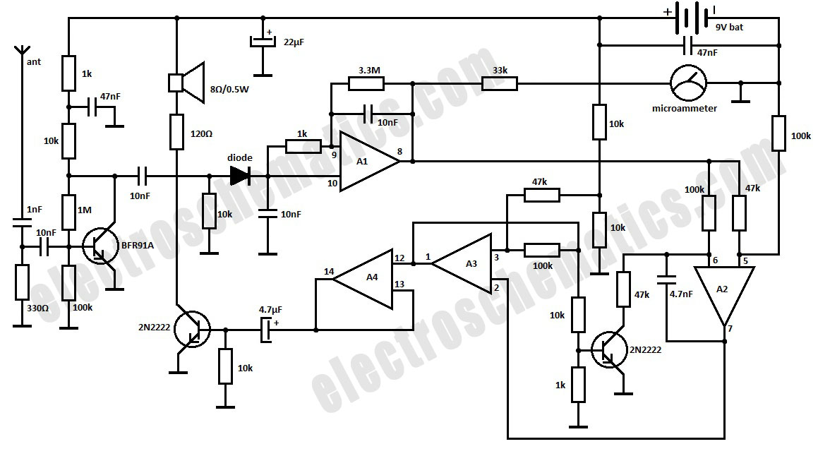
This is a simple RF bug detector designed to identify spy bugs, capable of operating up to 2 GHz. Below are some essential components required for this circuit. The RF bug detector circuit functions by utilizing radio frequency signals...
Low distortion bass and treble control for an amplifier. Circuit diagram. Electronics project. The low distortion bass and treble control circuit is designed to enhance the audio quality of an amplifier by allowing precise adjustments to the low and high-frequency...
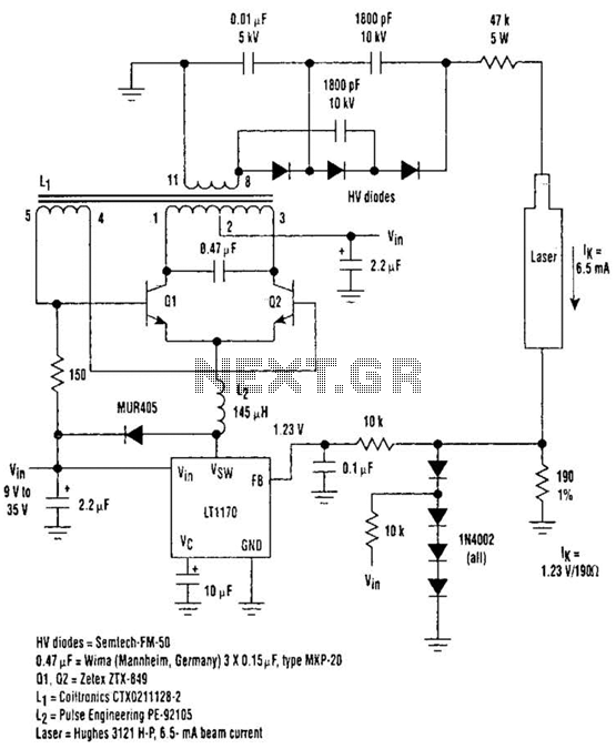
Driving Helium-Neon lasers can be greatly simplified using this power supply configuration. When power is applied, the laser does not conduct, and the voltage across the 190-ohm resistor is zero. However, a resonant circuit and a voltage tripler then...
An inverter is introduced which primarily utilizes a MOS field-effect transistor in conjunction with a conventional power transformer. The output power of the inverter is determined by the specifications of both the MOS field-effect transistor and the transformer, thereby...
The call is triggered by the position sensing circuit, which activates the control circuit and SOS alarm circuit. This system is designed for critically ill patients or to assist disabled individuals in the event of a fall. A position...
Commercial FM demodulation occurs at an intermediate frequency (IF) of 10.7 MHz. With a frequency deviation of ±75 kHz, the deviation of the IF carrier is approximately ±0.7%. This deviation allows for the conversion of FM to AM or...