
Bass-treble tone control circuits

The low distortion bass and treble control circuit is designed to enhance the audio quality of an amplifier by allowing precise adjustments to the low and high-frequency response. This circuit typically utilizes operational amplifiers (op-amps) configured in a tone control arrangement, which can effectively modify the amplitude of bass and treble frequencies while minimizing distortion.
In a typical implementation, the circuit may include a dual op-amp configuration where one op-amp is dedicated to bass control and the other to treble control. The frequency response can be adjusted by varying the feedback and gain settings of each op-amp. Passive components such as resistors and capacitors are strategically placed to define the cutoff frequencies for the bass and treble bands.
For instance, the bass control section can be designed with a low-pass filter configuration, where a potentiometer allows the user to increase or decrease the gain of frequencies below a certain threshold, typically around 100 Hz. Conversely, the treble control section employs a high-pass filter to boost or attenuate frequencies above a specified cutoff, often around 3 kHz.
The circuit diagram illustrates the connections between the op-amps, power supply, input, and output stages. Power supply decoupling capacitors are also included to ensure stable operation and reduce noise. Additionally, a bypass capacitor may be employed to filter out high-frequency noise from the power supply lines, further enhancing the performance of the circuit.
Overall, this low distortion bass and treble control circuit is an essential component for audiophiles and audio engineers looking to customize their audio experience by achieving a balanced sound profile tailored to individual preferences.Low distortion bass and treble control for amplifier. Circuit diagram. Electronics projectt.. 🔗 External reference
Related Circuits
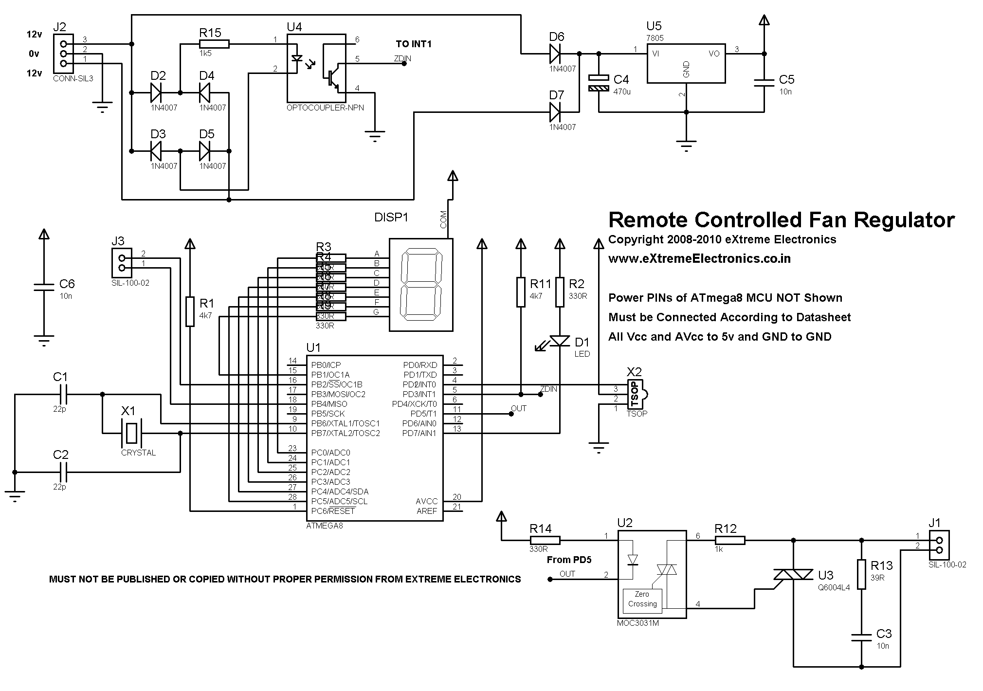
A detailed DIY remote-controlled AC fan regulator with 10-stage speed control. It is built using the ATmega8 microcontroller, and includes full source code and PCB layout. This project involves designing a remote-controlled AC fan regulator that allows users to adjust...
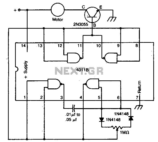
The circuit utilizes a 4011 CMOS NAND gate, a pair of diodes, and an NPN power transistor to create a variable duty-cycle DC source. By adjusting the speed control, the average voltage applied to the motor can be varied,...
The LM4844 is an integrated audio subsystem designed for stereo cell phone applications. Operating on a 3.3V supply, it combines a stereo speaker amplifier delivering 495mW per channel into an 8Ω load and a stereo OCL headphone amplifier delivering...
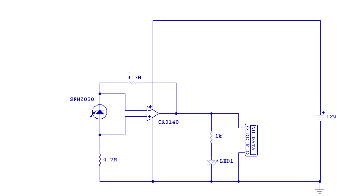
As I was developing my IR Extender Circuit, I needed to find a way of measuring the relative intensities of different Infra red light sources. This circuit is the result of my research. I have used a photodiode, SFH2030...
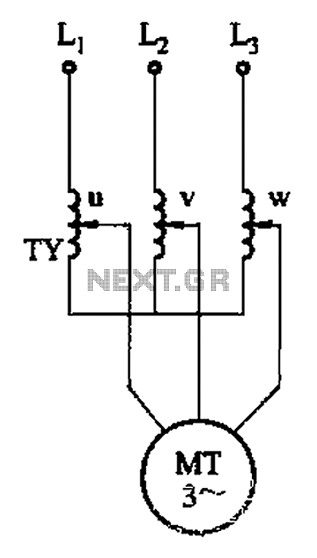
The circuit depicted in Figure 3-176 illustrates an adjustment method that allows the motor to operate at equilibrium. The adjustment range is relatively wide; however, it necessitates a three-phase voltage regulator, which incurs higher input costs. The circuit design in...
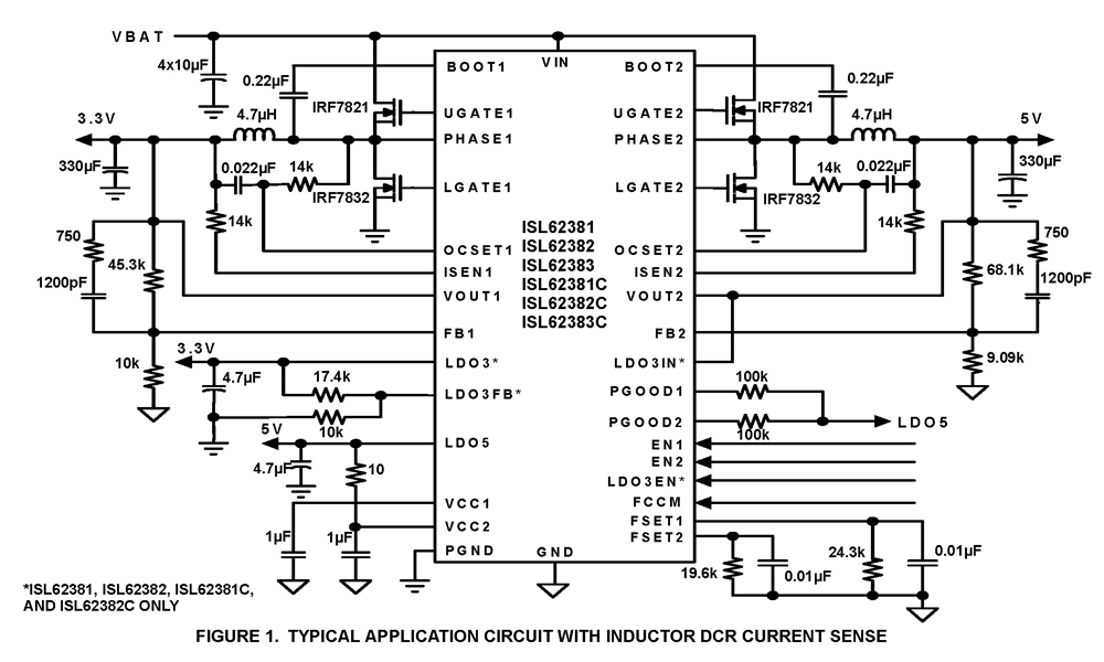
The ISL62381, ISL62382, ISL62383, ISL62381C, ISL62382C, and ISL62383C family of controllers generate supply voltages for battery-powered systems. These controllers include two pulse-width modulation (PWM) controllers, adjustable from 0.6V to 5.5V, and two linear regulators, LDO5 and LDO3, that generate...