
Adjustable DC power supply circuit

The adjustable DC power supply circuit is designed to provide a stable output voltage that can be tailored to meet specific requirements. The circuit begins with a step-down transformer, which reduces the input AC voltage to a lower AC voltage suitable for rectification. The transformer is selected based on the desired output voltage and current specifications.
Following the transformer, a rectifier bridge composed of four diodes (VD1 to VD4) converts the AC voltage to pulsating DC. The rectifier bridge is configured in a full-wave arrangement, ensuring efficient conversion and minimizing ripple voltage. The output from the rectifier is then smoothed using a capacitor to reduce voltage fluctuations, providing a more stable DC voltage.
The heart of the circuit is the voltage regulator, which maintains the output voltage at the desired level despite variations in input voltage or load current. The adjustment potentiometer (RP, 5.1 kΩ) is connected to the voltage regulator, allowing users to fine-tune the output voltage within a range of 2.5 V to 24 V. This feature is particularly useful for applications requiring different voltage levels, such as powering various electronic devices or experimental setups.
For optimal performance, careful consideration should be given to the selection of components, including the transformer rating, diode specifications, and capacitor values. Additionally, heat dissipation must be addressed, particularly in the voltage regulator, to prevent thermal shutdown or damage.
Overall, this adjustable DC power supply circuit is a versatile solution for providing variable DC voltages, suitable for a wide range of electronic applications.Adjustable DC power supply circuit Shows an adjustable DC power supply circuit, which is composed of step-down transformer T, rectifier bridge pile (VD1 ~ VD4) and other parts of the voltage regulator circuit, the adjustment potentiometer RP (5.i kfl), the output voltage varies between 2.5-24 V.
Related Circuits
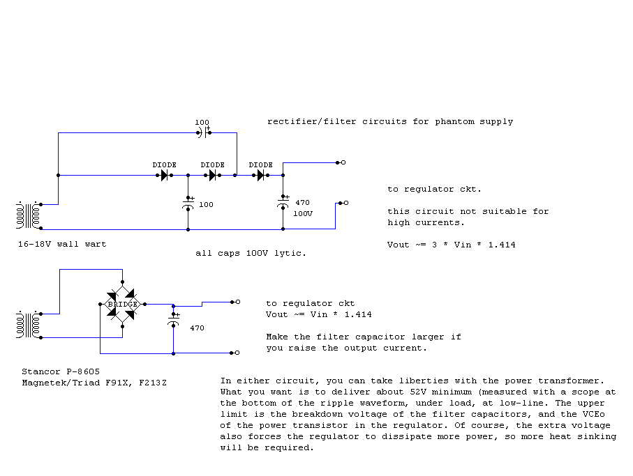
An RF condenser design powered by 12V was supplied to the microphone through the microphone cable using a phantom circuit. This marks the first known application of a phantom circuit for microphone powering. Around 1970, Neumann introduced the Fet-80...
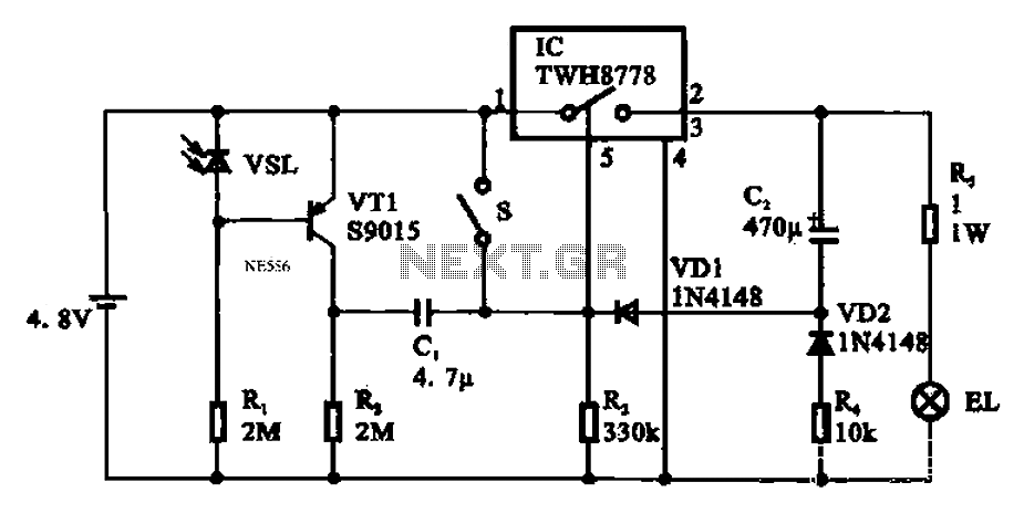
Automatic emergency lamp circuit featuring an electronic switch integrated circuit. This circuit is designed for automatic emergency lighting. The system operates based on ambient light conditions; when light levels are low at night, the circuit activates the emergency lamp....
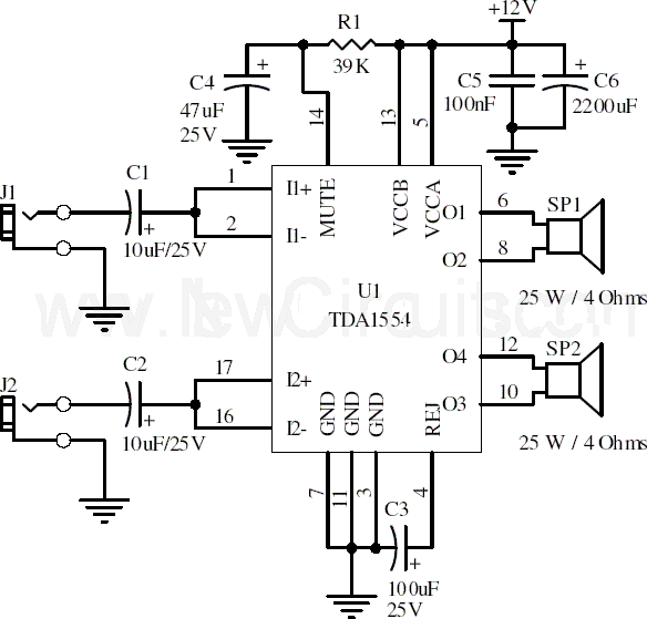
This document presents a 22-watt stereo audio power amplifier circuit diagram utilizing the TDA1554 integrated circuit from NXP Semiconductors (formerly known as PHILIPS Semiconductors). The circuit is designed to amplify stereo signals effectively. It dissipates approximately 28 watts of...
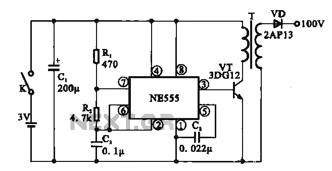
This circuit illustrates a simple boost converter, which is powered by an oscillating signal generated by the NE555 timer. The signal is amplified through a VT transistor to drive a booster transformer. This step-up transformer increases the oscillating signal,...
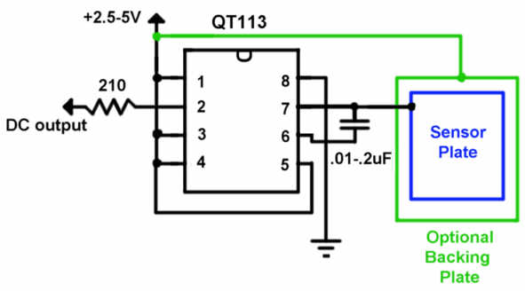
The QT113 is a capacitance touch sensor that does not require AC line voltage to operate. Instead, it detects changes in capacitance caused by the proximity of a user’s body. A sensor plate measuring 2 inches square can sense...
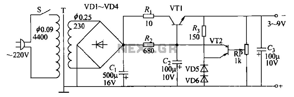
A 3-9V adjustable 100mA power supply is presented, featuring a series regulator circuit that utilizes amplifier tubes. The output voltage can be continuously adjusted between 3V and 9V, with a maximum output current of 100mA, making it suitable for...