
IR Remote Control Tester Circuit

The IR Remote Control Tester Circuit is designed to verify the functionality of infrared remote controls. The core component of this circuit is the transistor T1, which plays a crucial role in detecting the infrared signals emitted by the remote control. When the remote is activated, it sends a series of infrared pulses, which are picked up by an infrared receiver diode in the circuit.
The circuit typically consists of the following components: an infrared receiver diode, a transistor (T1), resistors, a power supply, and a data output pin. The infrared receiver diode converts the incoming infrared signals into electrical signals. When the infrared pulse is detected, it causes the transistor T1 to conduct. This conduction occurs specifically during the negative pulse period of the infrared signal, allowing for the detection of the signal's presence.
The data output pin is used to provide a visual or audible indication of the detected signal. This could be connected to an LED, which lights up when the remote control is functioning correctly, or to a buzzer that sounds when a signal is received. The circuit can be powered by a standard DC power supply, ensuring that it operates effectively for testing purposes.
In summary, the IR Remote Control Tester Circuit serves as a practical tool for troubleshooting and verifying the operation of infrared remote controls by utilizing a simple yet effective design that highlights the key components and their functions.The following circuit shows about IR Remote Control Tester Circuit. Features: transistor T1 conducts during negative pulse period, data output pin . 🔗 External reference
Related Circuits
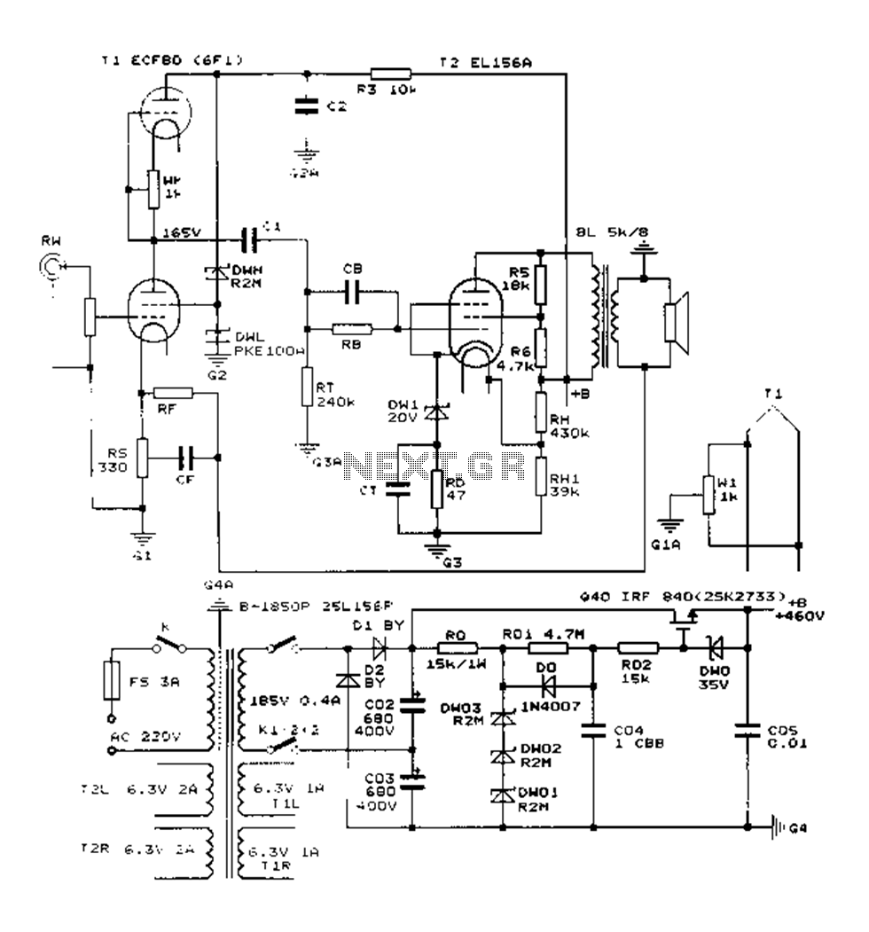
The Danji mellow sound is characterized by its transparent and natural quality, offering a sweet and sincere listening experience that is tireless over long durations and rich in humane color. Tube amplifiers have become an audiophile's companion and are...
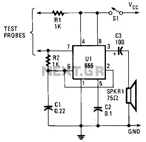
The continuity tester supplies a voltage through the positive probe to the circuit being tested, while the negative probe acts as the return line. The voltage that returns to the tester via the negative probe activates the circuit, providing...
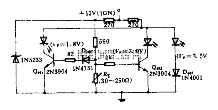
The circuit diagram illustrates how an oil pressure sensor is transformed into a variable resistor, denoted as Rt. Variations in Rt lead to changes in the biasing of each transistor, which in turn controls three LEDs (red, yellow, and...
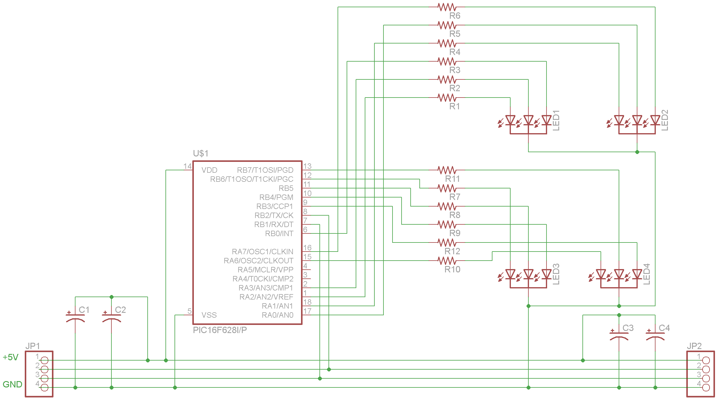
The complete schematic for the driver is provided. A PIC16F628 microcontroller has been selected due to its low cost, internal oscillator (4 MHz), and built-in USART. It is important to note that there is an error in the schematic;...
This circuit serves as a decorative element or indicator, featuring adjustable flashing or dancing speeds of LEDs and the ability to create various light patterns. It consists of two astable multivibrators: one formed by transistors T1 and T2, and...
The initial PIC program utilizing the C language demonstrates how to blink a single LED using a PIC microcontroller with a C program. This serves as an introduction to C programming for PIC microcontrollers. The circuit for blinking an LED...