
Adjustable Symmetrical Power Supply ?± 125 until ?±30V 1A circuit

The voltage converter employs a three-terminal voltage regulator, which is a widely used component in power supply circuits for its reliability and ease of use. The input voltage of ±35V is fed into the regulator, which is configured to provide a stable output voltage within the specified range of ±1.25V to ±30V.
The design typically includes a filtering stage at the input to smooth out any fluctuations in the supply voltage, ensuring that the regulator receives a stable input for optimal performance. Capacitors are used at the input and output terminals of the regulator to filter high-frequency noise and provide transient response stability.
To achieve the desired output voltage, the voltage regulator may be paired with a resistor divider network or adjustable potentiometer, allowing for fine-tuning of the output voltage according to specific application requirements. The thermal performance of the regulator should also be considered, as it may require a heat sink to dissipate excess heat generated during operation, especially when the load draws significant current.
Protection features such as overcurrent protection and thermal shutdown may be integrated into the design to enhance reliability and prevent damage to the components. Additionally, the layout of the circuit board should minimize the length of the connections to reduce parasitic inductance and capacitance, which can affect performance.
Overall, this voltage converter design effectively transforms a high input voltage to a lower, stable output voltage suitable for various electronic applications, leveraging the advantages of three-terminal voltage regulators in its implementation.This is the voltage converter to get the voltage of ±1,25-30V from the input voltage of ±35V. I am using the 3 terminal voltage regulator for the voltage to be changed in this unit.. 🔗 External reference
Related Circuits
This circuit illustrates a Go-No/Go Tester Circuit utilizing a 555 Timer IC. Features include a more advanced unit with a precise timed testing procedure. The Go-No/Go Tester Circuit is designed to evaluate components or assemblies by providing a simple pass/fail...
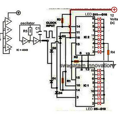
Decorative lights arranged in various moving patterns are visually appealing and have gained significant popularity in today's world. While more complex lighting arrangements may require the use of microcontroller ICs, simpler yet captivating light effects can be generated using...
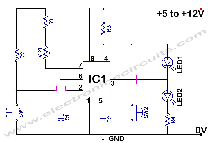
The 555 Timer Time Delay Circuit uses LEDs to visually indicate the status of the circuit at any moment. The operation begins when the reset switch, SW2, is activated. The 555 Timer is a versatile integrated circuit widely used for...
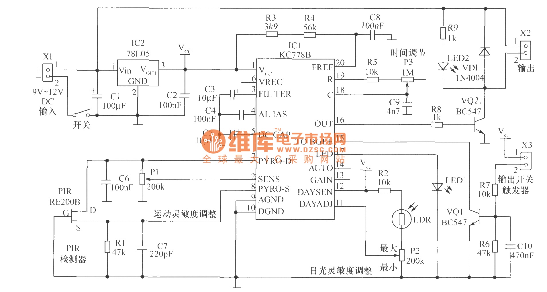
The core component of the motion detection circuit is the motion detection chip IC1 (KC778B). The signal frequency from the PIR sensor is low, ranging from 0.1Hz to 10Hz, while the bandwidth is quite broad, which the chip will...
The purpose of this report is to provide background and findings of our senior project. We will discuss four steps that we used to complete our final project. The four steps of our project were research and development, design,...
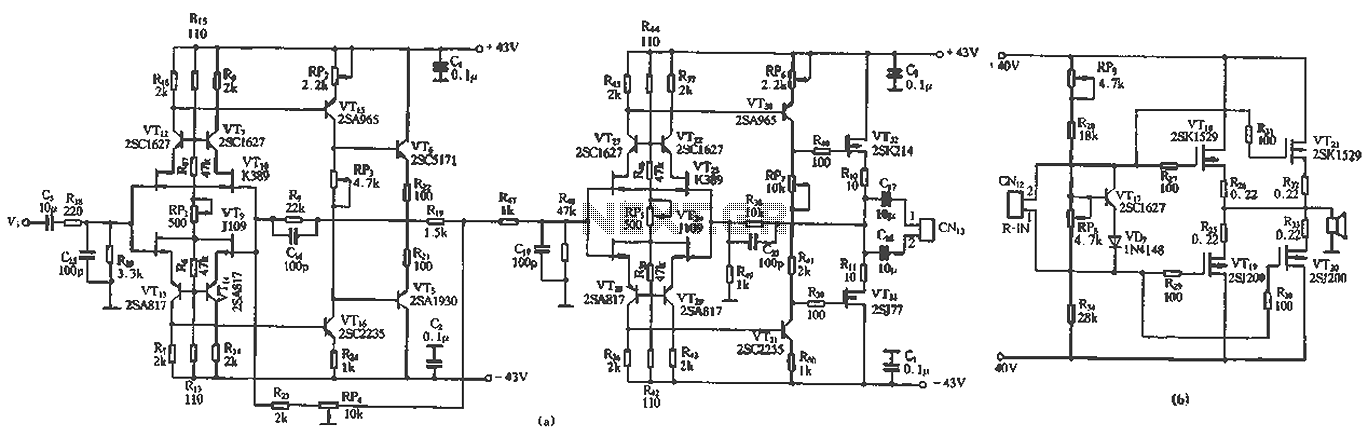
The circuit design features a unique technology and a reasonable structure utilizing all-discrete components with a Class A FET output. The complete circuit includes an input stage, an output stage, and a power level circuit to enhance performance, along...