
Go-No/Go Tester Circuit With 555 Timer IC

The Go-No/Go Tester Circuit is designed to evaluate components or assemblies by providing a simple pass/fail indication. The core of the circuit is the 555 Timer IC, which is configured in a monostable mode. In this configuration, the circuit generates a single output pulse of a specified duration when triggered.
The circuit typically includes an input section where the device under test (DUT) is connected. This input section may include a switch to initiate the testing process. When the switch is closed, the 555 Timer is triggered, causing it to output a high signal for a predetermined time, which can be adjusted by changing the resistor and capacitor values connected to the timer.
The output from the 555 Timer can be connected to an LED or a buzzer, providing visual or auditory feedback to indicate whether the DUT passed or failed the test. A green LED may signify a "Go" condition, while a red LED indicates a "No-Go" condition.
To enhance the functionality of the circuit, additional components can be integrated. For instance, a potentiometer can be included to allow for fine-tuning of the timing interval, accommodating various testing requirements. Furthermore, the circuit can be powered by a standard battery or DC power supply, ensuring portability and ease of use.
Overall, the Go-No/Go Tester Circuit with a 555 Timer IC represents an efficient solution for testing electronic components, providing clear and immediate feedback on their operational status.This circuit shows about Go-No/Go Tester Circuit With 555 Timer IC. Features: more advanced unit with a precise timed testing procedure. .. 🔗 External reference
Related Circuits
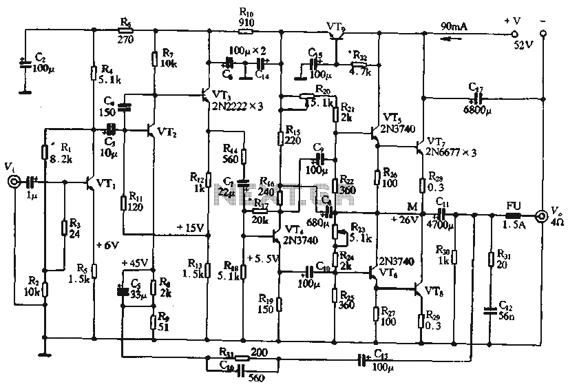
The circuit depicted in the figure is a highly technical OTL (Output Transformer-Less) amplifier circuit. It features a frequency response range of 10 Hz to 100 kHz and exhibits a total harmonic distortion of less than 0.1%, which is...
The circuit features an adjustable prestage utilizing the AF279 transistor, while the natural oscillation mixer stage employs the AF280 transistor. The power circuit is mounted on a board with copper coating. The main coil specifications are as follows: L1,...
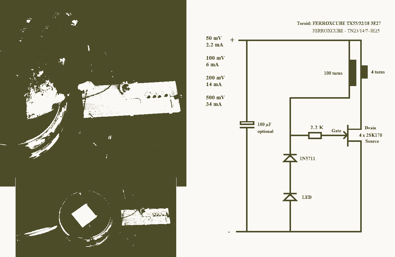
A 25mV Joule Thief powered by a Peltier device that utilizes body heat. The 25mV Joule Thief circuit is an innovative energy harvesting solution that converts the minimal voltage generated by a Peltier device into usable electrical energy. The Joule...
To complement the 60 Watt MOSFET audio amplifier, a high-quality preamplifier design was necessary. A discrete components topology using +24V and -24V supply rails was chosen, minimizing the transistor count while still achieving low noise, very low distortion, and...
This is a straightforward infrared detector circuit designed to detect infrared light. The circuit comprises only three components: an RS-276-145 photo transistor, a 330-ohm resistor, and a general-purpose LED (Light Emitting Diode). When the photo transistor receives infrared light...
Nissan Sentra 1.6 Liter Manual Transmission Starter Circuit Wiring Diagram. The Nissan Sentra 1.6 Liter manual transmission starter circuit wiring diagram provides a visual representation of the electrical connections involved in the starting system of the vehicle. This diagram is...