
555 Timer Time Delay Circuit

The 555 Timer is a versatile integrated circuit widely used for generating precise timing and oscillation. In a time delay circuit configuration, it can be employed to create a delay before an output signal is activated or deactivated. This circuit typically includes a 555 timer IC, resistors, capacitors, a reset switch, and LEDs for status indication.
The circuit functions by charging a capacitor through a resistor, with the 555 timer configured in monostable mode. When the reset switch (SW2) is pressed, it triggers the 555 timer, causing the output pin to go high for a duration determined by the resistor and capacitor values. The time delay \( T \) can be calculated using the formula \( T = 1.1 \times R \times C \), where \( R \) is the resistance in ohms and \( C \) is the capacitance in farads.
The LEDs connected to the output pin serve as visual indicators. When the output is high, one LED may light up, indicating the active state of the circuit. Conversely, when the timer completes its cycle and the output goes low, another LED may illuminate, signifying that the delay period has ended.
To ensure proper operation, it is essential to select appropriate resistor and capacitor values that provide the desired time delay while considering the forward voltage and current ratings of the LEDs. Additional components, such as diodes, may be incorporated to protect the circuit from voltage spikes or to ensure proper current flow through the LEDs.
This configuration allows for a straightforward yet effective way to monitor the operation of the circuit visually, making it suitable for various applications, including timers, alarms, and other delay-related functionalities in electronic systems.555 Timer Time Delay Circuit LEDs indicate at a glance what the status of the circuit is at any given moment. Once the reset switch, SW2, makes.. 🔗 External reference
Related Circuits
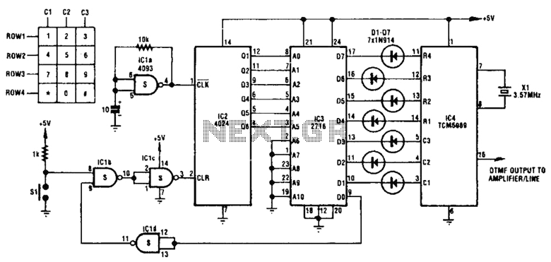
This circuit utilizes inexpensive, commonly available components to generate a precise dial tone for telephone applications. The Intel 82C54 timer-counter (U1) produces square wave signals at frequencies of 350 Hz and 440 Hz, which are subsequently filtered by resistors...
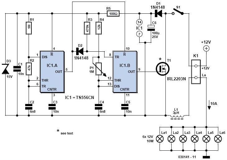
is circuit was requested from an email. It will allow your car headlights to flash on and off at the same time or it will cause them to flash alternately. The circuit is based on the 555 timer. It...
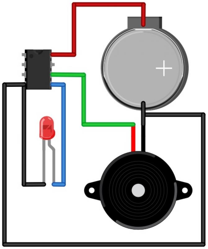
The Morse Beepy is a circuit designed to be simple and affordable, making it suitable for both children and adults as an introductory soldering project. It can be assembled and programmed within fifteen minutes to beep and blink a...
A light dimmer is quite uncommon in a caravan or on a boat. This document outlines how to create one, allowing for mood adjustment when needed. A light dimmer circuit is an essential component for enhancing the ambiance in confined...
The following circuit illustrates a Solar Tracker Circuit Diagram. This circuit is based on the LM339 integrated circuit. Features include a 10nF ceramic capacitor (103z) and a 1MΩ resistor. The Solar Tracker Circuit utilizes the LM339 quad comparator IC to...
A 12V battery pack from a PowerWheels car is used alongside two wooden planks with several nails driven through them. Each nail is wrapped with speaker wire that connects to ignitors, while the other end returns to a central...