
Adopt DC/DC converter of PWM technical control

The on-off type DC/DC converter is a versatile power management solution that utilizes two primary modes of operation: a constant duty cycle mode and a pulse frequency modulation mode. In the constant duty cycle mode, the converter maintains a fixed on-time for the switching element, while the pulse frequency modulation mode adjusts the frequency of the pulses while keeping the on-time constant. This dual-mode capability allows the converter to be optimized for various load conditions and efficiency requirements.
The PWM DC/DC converter functions by controlling a gas switching tube to convert a direct current voltage into a high-frequency square wave. This square wave is then transformed back into a direct current voltage through a rectification process, often involving a smoothing circuit to ensure a steady output. The architecture of the converter comprises several key components, including the power gas switching tube, rectifying elements (often diodes), a smoothing circuit (typically capacitors), and a PWM control circuit that orchestrates the operation of the switching elements.
Electrical isolation between the input and output is critical for safety and performance, which is typically achieved using a transformer. This transformer not only provides isolation but also allows for voltage step-up or step-down as required by the application. The operating principle of the PWM DC/DC converter leverages high-frequency operation, which enables the miniaturization of magnetic components such as inductors and transformers. This is particularly advantageous in applications where space is at a premium.
The converter operates at a fixed switching frequency, with various control signals sampled from different points in the circuit, including output voltage, input voltage, output current, inductive voltage, and the current through the switching element. These sampled signals can be utilized to create feedback loops for voltage regulation, current regulation, and maintaining power stability. Additionally, the system can incorporate features such as overcurrent protection and magnetic bias resistance to enhance reliability and performance.
The control circuit generates a driving signal for the PWM control based on the selected feedback mode. The output voltage is typically used as the primary control signal, which is processed through an operational amplifier circuit. This operational amplifier amplifies the difference between the actual output voltage and a predetermined reference voltage, thereby ensuring precise voltage regulation during steady-state operation. The design philosophy emphasizes achieving a high low-frequency gain while managing high-frequency noise to maintain system stability and dynamic response.
In summary, the on-off type PWM DC/DC converter represents a sophisticated power conversion solution that effectively balances efficiency, size, and performance through its dual-mode operation and advanced control strategies.The on-off-type DC/ DC converter has two kinds of operating modes: One kind keeps the switch duty cycle worker constant, the controlled switch turns on time sha. Pulse length modulation PWM of n Way; Ton is constant that another kind keeps turning on time, change the pulse frequency modulation PFM of several of duty cycle of switch Way.
Pulse leng th modulation PWM DC/ DC converter is through controlling the gas switching tube to repeat a kind of direct-current volts electric current once of operating mode of the ON/OFF Transform high-frequency the intersection of rectangular wave and voltage to Electric current, And then turn into another direct-current volts after commutating Fructus Mali pumilae Electric current Output. PWM DC/ DC converter made up of power gas switching tube, kenotron, smoothing circuit and PWM controlling circuit, etc.
Its input, exporting one while needing to carry on the electrical isolation, can adopt the voltage transformer to isolate and rise, step down. The operating principle of PWM DC/ DC converter is shown as in Fig. 1. Because of the improvement of the operating frequency of the switch, magnetic elements such as filtering inductor L, voltage transformer T, etc.
and Filtering capacitance C, etc. can be by miniaturization. PWM DC/ DC invariable generally in switching frequency of converter, control sample of signal as follows, output voltage, input voltage, output current, outputting inductance voltage, switching element crest current. Can form monocyclic ring, double ring or multiloop feedback system by these signals, in order to realize the purposes of voltage regulation, current regulator and invariable power, can realize the function of some subsidiary overcurrent protection, resisting magnetic biasing, flowing etc.
at the same time. Generally speaking, the positive excited type stabilized voltage supply main circuit of high-frequency switch can use the chopper reduced representation of depressurization shown in Fig. 3, UG shows PWM of the controlling circuit outputs the driving signal. According to the modal difference of PWM feedback control chosen, the input voltage UIN, output voltage UOUT, switching element electric current clicked by b and drawn in the circuit, inductive current Clicked drawing or d by c and clicked drawing Can be regarded as the control signal of taking a sample.
The output voltage UOUT is here as controlling the of sample of signal, usually deals with through the circuit shown in Fig. 4, receive the signal UE of the voltage, UE is dealt with or sent into PWM control device directly again.
In the circuit shown in Fig. 4, voltage operation amplifier e/ a Act on as follows. Amplify and feedback the difference of output voltage and given voltage UREF, in order to guarantee the precision of voltage regulation at the time of the steady state. It is the infinity in theory that the direct current of this operational amplifier enlarges the gain to noise temperature ratio, in fact it is the gain to noise temperature ratio of broken-loop amplification of operational amplifier.
The direct-current volts signal of the switching noise composition of multiply frequency changes into having comparison of certain amplitude to relatively have the stabilized voltage supply main circuit Ausgang of the high-frequency switch by the way Clean Direct-flow feedback control signal UE, Namely keep the direct-flow low frequency composition, decay and exchange the high-frequency composition. Because switching noise is high-frequency, the amplitude is relatively large, noise attenuation of switch is not enough that high-frequency, then the steady state is feedbacked unstably; If high-frequency switch noise attenuation is too big, then dynamical response is relatively slow.
Though is contradictory, the basic design philosophy of the voltage error operation amplifier is still that low-frequency gain should be high, the high-frequency 🔗 External reference
Related Circuits
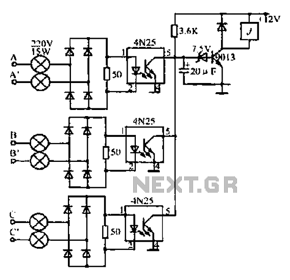
A, B, and C are used for a large power split-phase system. The A + BC range generator phase line features an A-A indole path string containing two 220V/15W bulbs. The bulbs recover based on macro instructions from J...
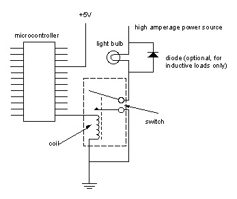
Digital output from a microcontroller is typically a low-amperage signal. For example, when a pin is set HIGH on the microcontroller (in Wiring/Arduino, it is digitalWrite(somePin, HIGH);), the voltage from that pin is usually +3.3V or +5V, with the...
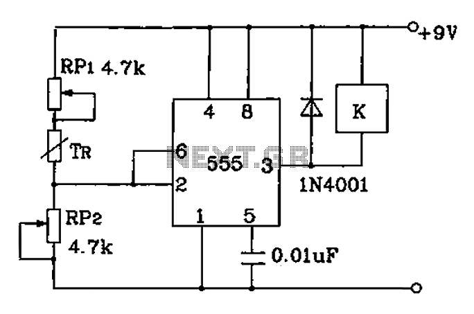
Adjust RP1 and RP2 to set the preset temperature control point. The 555 circuit is configured as a Schmitt inverter circuit that automatically controls a relay device. This forms part of the T-121 temperature control circuit, which includes a...
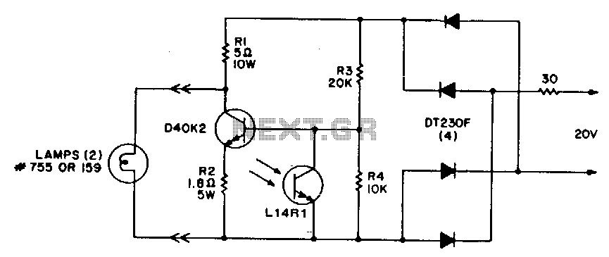
This circuit offers a cost-effective method for controlling light levels. Power for the circuit is derived from a relatively high source impedance transformer or motor windings, which are typically used to drive low-voltage lamps in these applications. It is...
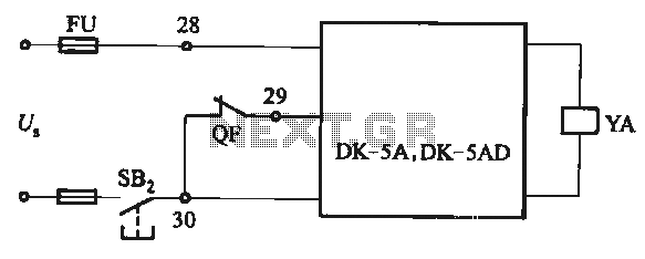
The DK-5A and DK-5AD AC power control circuit is illustrated in Figure 6-77. The figure includes a closing button (SBz) and a line (YA) connected to the closing electromagnet coil (U). This circuit is designed for the operation of...
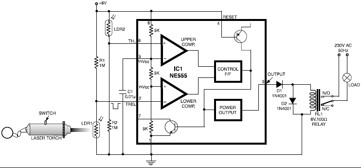
This circuit is designed around a 555 timer and utilizes a minimal number of components. Its simplicity allows even beginners to easily assemble and operate it as a control device. A readily available laser pointer can be used to...