
laser controlled on off switch

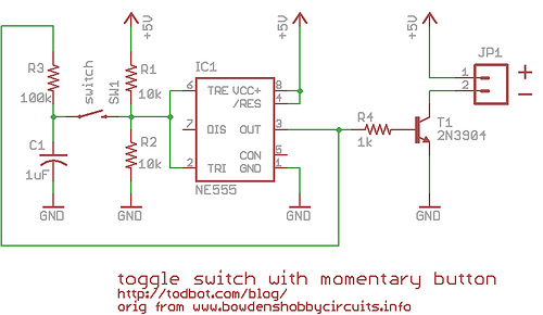
The circuit primarily consists of a 555 timer configured in a monostable or astable mode, depending on the desired application. The LDRs serve as light sensors that detect the laser beam's presence. When the laser beam strikes LDR1, it reduces the resistance of the sensor, triggering the 555 timer to activate the relay. This relay acts as a switch, allowing a higher power device, such as a fan or audio system, to be turned on. Conversely, when the laser beam is directed at LDR2, it similarly activates the 555 timer but in a manner that resets the relay, thus turning off the connected device.
To ensure optimal performance, the circuit should be housed in a protective enclosure to prevent interference from ambient light, as the effectiveness of the LDRs diminishes in well-lit conditions. The choice of components, including the relay specifications and the values of resistors and capacitors in the 555 timer circuit, should be tailored to the specific load requirements of the devices being controlled. Power supply considerations are also essential; the circuit may be powered by a standard battery or a DC power supply, depending on the application.
In summary, this circuit offers a practical solution for remote control of various electrical devices, with significant versatility and ease of use, making it suitable for a wide range of applications in home automation and other electronic control systems.This circuit is built around a 555timer using very few components. Since the circuit is verysimple, even a novice can easily build itand use it as a controlling device. A laser pointer, now easily available in the market, can be used to operate this device. This circuit has been tested in operationalconditions from a distance of500 metres and was fou nd to work satisfactorily though it can be controlledfrom still longer distances. Aiming(aligning) the laser beam exactly on tothe LDR is a practical problem. The circuit is very useful in switchingon/off a fan at night without gettingoff the bed. It can also be used forcontrolling a variety of other deviceslike radio or music system. The limitationis that the circuit is operational only in dark or dull-lit environments. By focussing the laser beam onLDR1 the connected gadget can be activatedthrough the relay, whereas by focussinglaser beam on LDR2 we canswitch off the gadget. 🔗 External reference
Related Circuits
The red laser line gradually sweeps across the object, which in this case is a Fabuland lamb head. Behind the scanned object, two planes positioned at a 90° angle provide a reference for the scanning software. These planes are...

This is a simple electronic circuit for a clap switch project. It is suitable for beginner electronics learners who enjoy experimenting with new projects. The circuit can turn on or off a 220V electronic device, such as a fan...
Most circuits operate based on a flip-flop principle. Instead of using a dedicated flip-flop chip, a 555 timer chip can be utilized, as it contains a single flip-flop and several comparators. After researching various resources, including Forrest Mims' electronics...
This is basically a Schmitt Trigger circuit which receives input from a cadmium sulfide photo cell and controls a relay that can be used to switch off and on a street lamp at dawn and dusk. I have built...
Currently, batteries are becoming increasingly powerful, serving as the sole energy source for portable electronic devices. The rapid evolution of battery technology has prompted manufacturers of electronic equipment to strive for reduced power consumption in their products, enabling them...
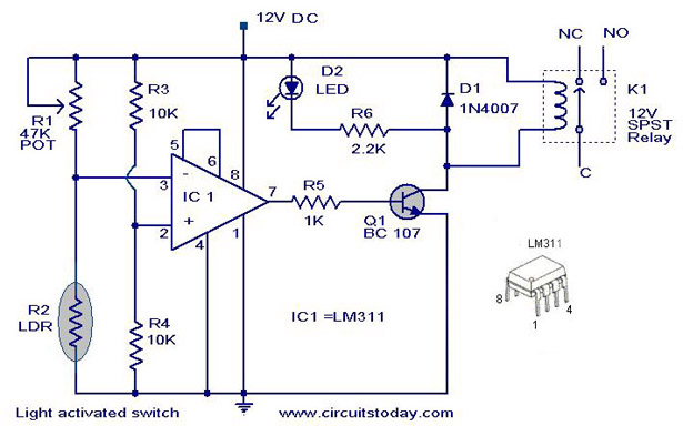
The following circuit illustrates a Light Activated Switch Circuit Diagram. This circuit is based on the LM311 integrated circuit, which functions as a voltage comparator. The Light Activated Switch Circuit utilizes the LM311 voltage comparator to control the switching of...