
ADP1821 Step Down DC-to-DC Converter

The ADP1821 is designed to efficiently convert a higher input voltage to a lower output voltage while maintaining high performance and efficiency. This device operates in a synchronous mode, allowing for reduced power loss and improved efficiency compared to non-synchronous designs. The PWM control scheme enables precise regulation of the output voltage, making the circuit suitable for various applications, including powering microcontrollers, sensors, and other electronic devices.
The circuit typically includes several key components: the ADP1821 IC itself, input and output capacitors, an inductor, and a diode. The input capacitors serve to stabilize the input voltage and reduce voltage ripple, while the output capacitors help maintain a steady output voltage with minimal ripple. The inductor is critical for energy storage and transfer; it smooths the current flowing to the load, helping to maintain a consistent output voltage.
In operation, the ADP1821 modulates the duty cycle of the switching signal to control the amount of energy delivered to the output. The feedback loop monitors the output voltage and adjusts the PWM signal accordingly, ensuring that the output remains stable despite variations in load current or input voltage. This feedback mechanism is essential for maintaining the desired output voltage under different operating conditions.
The design of the circuit should also consider thermal management, as the ADP1821 can generate heat during operation. Adequate heat sinking or thermal vias may be required to ensure reliable performance. Additionally, careful selection of the inductor and capacitors is important to optimize the transient response and minimize output voltage ripple.
Overall, the ADP1821 step-down DC-to-DC converter circuit is a robust solution for efficiently powering electronic devices from higher voltage sources, making it a valuable component in modern electronic design.This is a ADP1821 Step Down DC-to-DC Converter circuit. This circuit uses ADP1821 that is synchronous pulse-width-modulated (PWM), step-down controller,. 🔗 External reference
Related Circuits
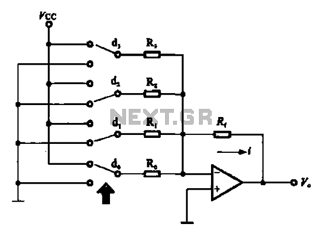
An A/D converter circuit can be represented by a simplified schematic, which illustrates a parallel type A/D converter. The term "median" refers to the number of bits in the digital signal output. The figure displays four A/D converters utilizing...

The power converter is situated in the underground installation of the LHC, positioned close to the loads to minimize cable losses. It is a high-current switch mode power converter, specifically designed to power superconducting loads that require only positive...
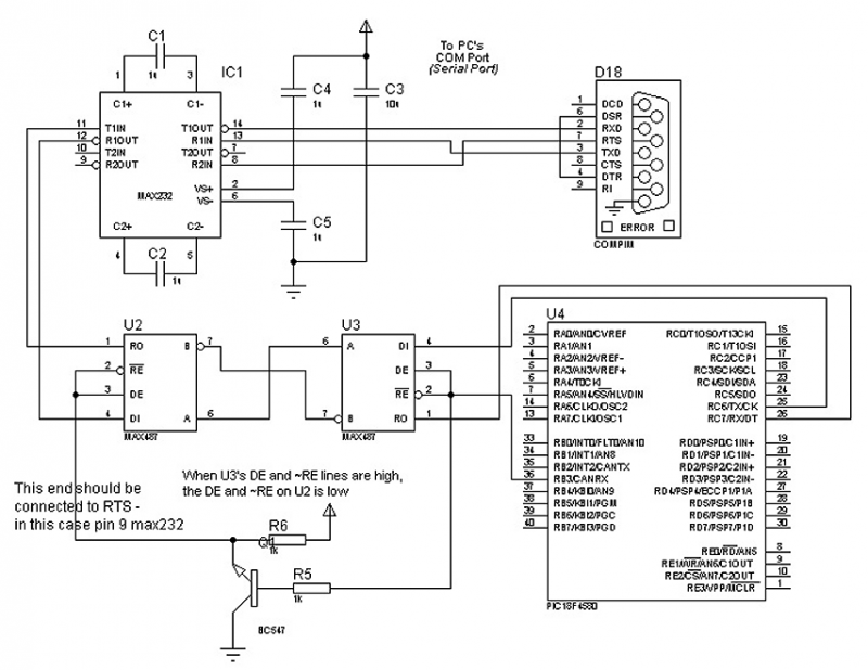
The circuit in Figure 1 is an RS-232/485 converter that uses the transmitted signal itself to control the flow. The circuit uses MAX232 and MAX483 interface circuits, IC1 and IC2 from Maxim Integrated Products to convert between the ICs'...
Stepper motors come in various versions and sizes, accommodating a range of operating voltages. This general-purpose controller is capable of functioning with voltages from approximately 5 V to 18 V, driving the motor with a peak voltage equal to...
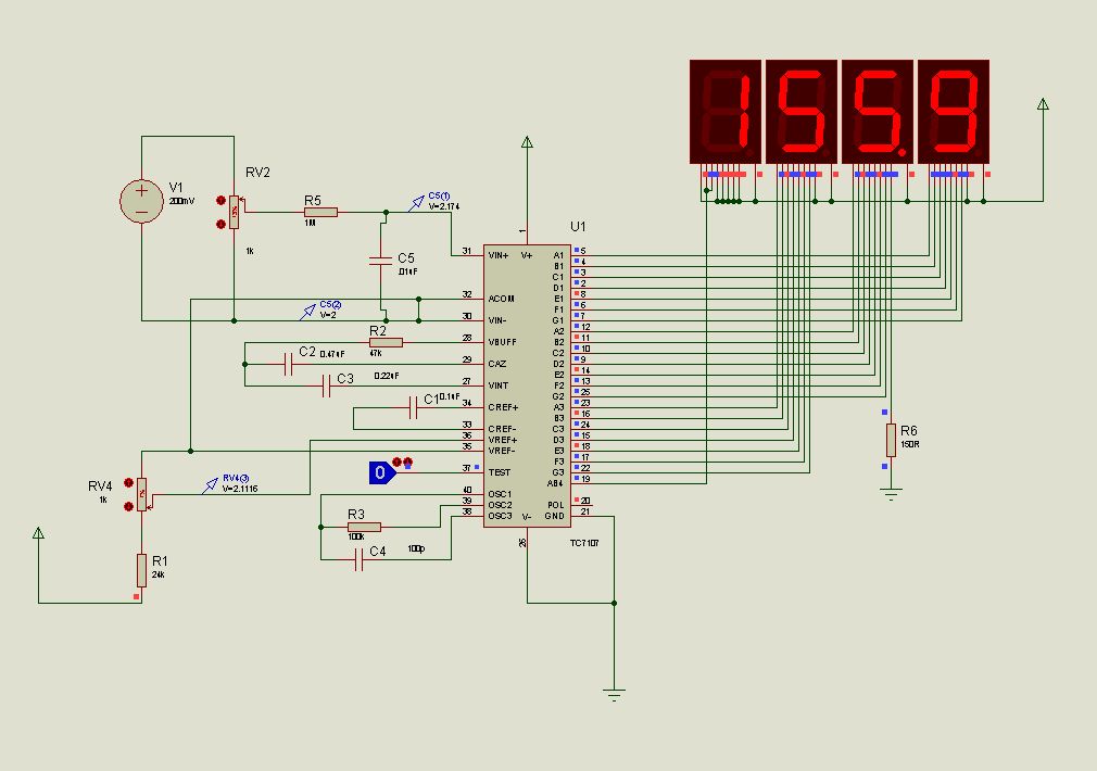
This document presents new models of a 3-digit common cathode (CC) and common anode (CA) multiplexed 3-digit voltmeter chip, specifically the TC7107 (ICL7107). It features a thumb switch with a common pin for BCD and hexadecimal outputs. The TC7107 is...
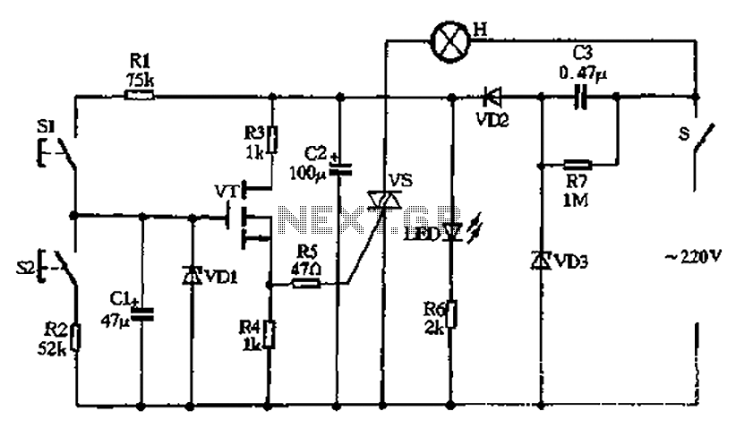
Capacitors C2 and C3, diodes VD2 and VD3, along with other components, form a simple capacitive half-wave rectifier buck power supply. The entire supply control circuit is managed by a switch (S), which can either be a standard small...