
Advertising lights controller circuit diagram 555

The decorative lamp control circuit utilizes a sophisticated arrangement of components to achieve dynamic lighting effects. At the heart of the circuit is a multivibrator formed by IC1 and passive components R1, R2, and C1, which generates a fundamental oscillation frequency. The frequency is determined by the formula f = 1.44 / (R1 + 2R2 C1), allowing for precise control of the output frequency, which is approximately 4Hz. This frequency serves as the basis for subsequent signal processing.
The frequency divider is implemented using IC2, which, along with its trigger circuit consisting of R3, R4, and C2, effectively reduces the frequency of the output from IC1 by half. This division is crucial for creating the necessary timing intervals for the subsequent logic operations. Similarly, IC3 operates to produce a square wave output at one-third the frequency of IC1, enabling further modulation of the lighting patterns.
The matrix circuit is pivotal in determining the overall behavior of the lighting system. It takes four distinct waveforms (A, B, C, D) and combines them through specific logic operations to yield three output states (Y1, Y2, Y3). These outputs are defined by the logic equations: Y1 = A + CD, Y2 = ABC + ACD + BCD, and Y3 = AB + AD. This logic matrix allows for intricate control over the lighting patterns, facilitating a wide range of decorative effects.
The triacs SCR1, SCR2, and SCR3 are employed to control the power delivered to the lights. By triggering these triacs with the output pulses from the matrix circuit, the system can selectively activate different combinations of lights, resulting in various decorative displays. The ability to modify the logical combinations within the matrix circuit further enhances the versatility of the lighting patterns, making the circuit suitable for a variety of decorative applications.
Overall, this decorative lamp control circuit exemplifies a well-designed system that integrates timing, logic, and power control to create visually appealing lighting effects. The modular nature of the components allows for adaptability and customization, making it an ideal solution for decorative lighting needs. As shown in FIG ad decorative lamp control circuit. The controller consists of a pulse generator, a frequency divider, matrix circuit and thyristor control circuit.IC1 and R1, R2, C1 and other components multivibrator, the oscillation frequency of f 1.44/(R1 + 2R2 C1, corresponding to the icon parameter is about 4Hz.IC2 and trigger circuit R3, R4, C2 and other components to achieve a square wave output of IC1 divided by two, as shown in (b) of the flip-flop circuit b shown .IC3 and R5, R6, C3 and other components to achieve the third of a square wave a of IC1 output frequency, as shown in ( .IC4 C shown in b), and the flip-flop circuit R7, R8, C4 and other components to achieve square wave output from IC1 a six-division, as shown in (b) of the D Fig. The matrix circuit A, B, C, D four different waveforms according to a certain logic combination, to obtain a combination of three types of state changes, the corresponding logic circuit matrix is: Y1 A + CD, Y2 ABC + ACD + BCD, Y3 AB + AD, and the relationship between the waveform Y1, Y2, Y3 is as shown in (c) in Fig.
With Y1, Y2, Y3 three pulses to trigger triac SCR1, SCR2, SCR3, you can make three lights work. The three lights different combinations, you get many of the decorative pattern or graphic ad shape. If you change the logical combination of the matrix, but also get more variation.The controller can be realized on three sets of lights to control, thus achieving the status of three combinations of variations, which can be used for decorative lighting applications.
Related Circuits
Men, in particular, appreciate the convenience of television remote controls, which can often lead to frustration for their female partners. Men seem to have a desire to understand what... The initial statement highlights a common dynamic in household technology usage,...
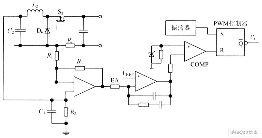
The circuit is capable of enhancing the system power factor to a value exceeding 0.99. It effectively reduces the waveform distortion of the input supply current, ensuring compliance with GB15144 standards, with a distortion index lower than level L....
The initial step often taken when learning about any microcontroller or embedded system is to make an LED blink. The circuit presented below illustrates the setup for interfacing an LED. Note: Due to the large dimensions of the circuit...

Useful for checking diodes, transistors, triacs, SCRs, resistors, and LEDs, this curve tracer should prove beneficial in the experimenter's lab. It displays the volt-ampere characteristic of a two-terminal device on an oscilloscope. This is a simple block diagram of...
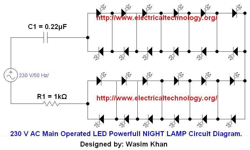
If you plan to use this circuit with a 110V 60Hz supply instead of a 230V 50Hz supply, or if you intend to modify this circuit, please refer to the section titled "Common Questions about this Circuit" found below...
This concept is somewhat different; however, a very simple method has been employed. Many people around the world search for UFOs by observing the sky, and often, wealthy individuals purchase expensive cameras to focus on the sky. In this...