
Air Flow Detector

The circuit operates on the principle of thermal resistance variation caused by airflow. The incandescent lamp's filament serves as both the heating element and the sensing element. The constant current source is critical as it ensures that the filament reaches a stable temperature, allowing for consistent operation. The heating effect causes the filament to reach a temperature where its resistance is predictable and can be accurately measured.
As airflow occurs over the filament, the cooling effect results in a decrease in temperature, which in turn lowers the resistance of the filament. This change in resistance is monitored by a comparator circuit. The comparator is configured to compare the voltage across the filament against a reference voltage. When the airflow cools the filament sufficiently to change its resistance, the voltage drop across the filament will fall below the reference voltage, triggering the comparator to activate an output signal.
In practical applications, the output of the comparator can drive an LED, providing a visual indication of airflow presence. For more advanced applications, the output can also be interfaced with an analog-to-digital converter (ADC) or a digital meter. This allows for quantification of airflow, enabling the circuit to be used in various measurement and control systems.
To enhance the circuit's capabilities, additional components may be introduced, such as filters to stabilize the output signal or calibration circuits to adjust the sensitivity of the airflow detection. The design can be further optimized by selecting a filament material with appropriate thermal characteristics or by employing a microcontroller to process the comparator output and provide more sophisticated data analysis. Overall, this circuit exemplifies a simple yet effective method for detecting and measuring airflow using basic electronic components.This simple circuit uses an incandescent lamp to detect airflow. With the filament exposed to air, a constant current source is used to slightly heat the filament. As it is heated, the resistance increases. As air flows over the filament it cools down, thus lowering it`s resistance. A comparator is used to detect this difference and light an LED. With a few changes, the circuit can be connected to a meter or ADC to provide an estimation on the amount of air flow. 🔗 External reference
Related Circuits
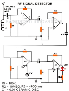
A simple electronic circuit project is presented that can be constructed by any school student for display at a school science fair. The proposed circuit is a high-gain operational amplifier (op-amp) amplifier designed to detect the slightest RF disturbances...
This circuit employs a synchronous demodulator to separate a 1 KHz signal from noise and measures the amplitude of the 1 kHz signals once a second at about 60 microvolts per count then sends the measurements via an RS-232...
The bat ultrasounds are picked up by the microphone SPKR1 and go through two stages of amplification at Q1 and Q2. Separately, a tunable (R12) single frequency is produced by the LM567 oscillator U1. The LM567 is a tone...
One LED monitors three levels: 50, 70 & 85 dB. Useful to detect too noisy environments. This circuit is intended to signal, through a flashing LED, the exceeding of a fixed threshold in room noise, chosen from three fixed...
A ringer interface circuit is designed to buffer the output of a central telephone system, which connects to multiple ringers distributed throughout a building. This circuit addresses an issue where the line overloads when ringing, requiring a reset. The...
This battery-powered metal detector utilizes four exclusive-OR gates from the 4030 CMOS integrated circuit. The gates are configured as twin oscillators, with a search coil acting as the inductance element in one of the oscillators. When the coil approaches...