
Air-Pressure Change Detector

The circuit operates by employing a piezoelectric detector, designated as BZ1, which is sensitive to changes in air pressure. When air pressure varies, BZ1 generates a corresponding voltage signal. This signal is then fed into an operational amplifier configuration, specifically U1A and U1B, where it is amplified to a suitable level for further processing. The design ensures that the frequency response is limited to low frequencies, which is ideal for applications where only slow variations in pressure need to be detected.
The amplified signal is subsequently routed to a rectification stage consisting of diodes D1 and D2. This rectification process converts the alternating current (AC) voltage signal generated by BZ1 into a direct current (DC) signal, making it suitable for driving the next stage of the circuit.
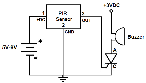
The rectified signal is then used to control a transistor, Q1, which acts as a switch. When the signal from the rectification stage exceeds a certain threshold, Q1 is activated, allowing current to flow to BZ2, the piezoelectric buzzer. BZ2 produces an audible sound as a response to the detected changes in air pressure, alerting the user to the event.
This circuit is particularly useful in applications such as pressure sensing in HVAC systems, environmental monitoring, or as an alert mechanism in various industrial processes. The combination of a piezoelectric detector and a buzzer provides a compact and efficient solution for pressure detection and alerting. A piezoelectric detector (BZ1) is used in this circuit to detect a change in air pressure. BZ1 produces a volt age that is amplified by U1A and UXB. Frequency response is limited to low frequencies. The signal is rectified by D1 and D2 and drives Ql, which activates BZ2, a piezoelectric buzzer.
Related Circuits
This project is useful if you wish to experiment with absolute phase, or are just interested in the possibilities of a polarity reversal circuit. In the case of absolute phase, many studies have shown that there can be an...
This is a circuit which I originally included in my book, 22 Tested Transistor Projects, published by Babani Press in 1976 (ISBN 0 900162 63 S). It is one I had great fun with. It uses the PUT Complimentary...
The circuit diagram of the Lie Detector is shown above. It consists of three transistors (TR1 to TR3), a capacitor (C1), two lights or LEDs (L1 & L2), five resistors (R1 to R5), and a variable resistor (VR1). This circuit...
This circuit will automatically switch on several mains-powered "slave" loads when a "master" load is turned on. For example, it will switch on the amplifier and CD player in a stereo system when the receiver is turned on. It...
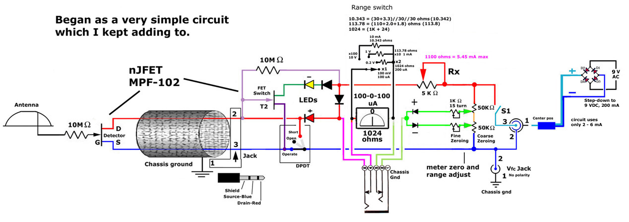
This post discusses the construction of multiple versions of JFET static charge detectors, highlighting observed differences that are not easily explained. The JFET (Junction Field Effect Transistor) static charge detector operates by utilizing the unique characteristics of JFETs to sense...
This is an alarm circuit that activates when motion is detected. Upon detection, the circuit triggers an alarm buzzer, which remains activated until the power is disconnected. This type of alarm circuit is commonly used to monitor areas for...