
JFET static detector

The JFET (Junction Field Effect Transistor) static charge detector operates by utilizing the unique characteristics of JFETs to sense variations in electric fields. The basic configuration typically includes a JFET connected in a common-source or common-drain arrangement, which allows for high input impedance and sensitivity to static charges.
In the design, the gate of the JFET is exposed to the environment, enabling it to detect electric fields generated by static charges. The output can be monitored through a load resistor connected to the drain, where the voltage variations reflect the presence of static charge. It is crucial to ensure proper biasing of the JFET to keep it in the active region, thus maintaining its sensitivity.
The differences observed in various versions of the static charge detectors could stem from several factors, including variations in JFET specifications, differences in the circuit layout, or the use of different materials for the gate. Additionally, environmental factors such as humidity and temperature can influence the performance of these detectors.
To enhance the performance of the static charge detector, it is advisable to implement a shielding mechanism to minimize interference from external electric fields. Furthermore, incorporating a feedback mechanism could stabilize the output and improve the accuracy of the readings.
Overall, JFET static charge detectors serve as valuable tools in applications requiring the detection of static electricity, and understanding the nuances of their design and operation is essential for optimizing their performance.Hello, this is my first post here. I built several versions of JFET static charge detectors and I`m seeing some differences I can`t explain so I`m.. 🔗 External reference
Related Circuits
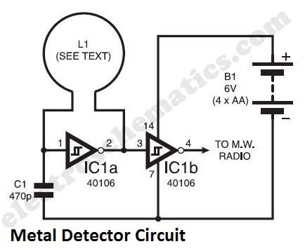
The metal detector circuit presented here exemplifies simplicity while demonstrating effective functionality. It utilizes a single 40106 hex Schmitt inverter IC, a capacitor, a search coil, and batteries. A connection from IC1b pin 4 must be made to a...
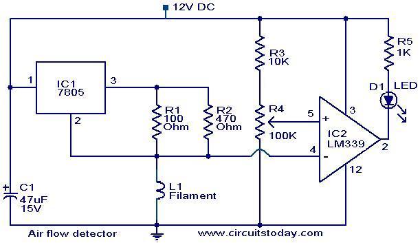
The filament of an incandescent bulb serves as the sensing component of the circuit. When there is no airflow, the resistance of the filament is low. In contrast, when airflow is present, the resistance decreases because the moving air...
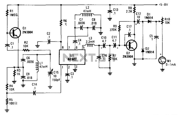
In this circuit, oscillator Q1 operates at approximately 15 kHz and provides input to mixer U1. U1 contains an internal oscillator that also runs at around 15 kHz. Capacitor C15 is employed to achieve zero-beat between both oscillators. When...
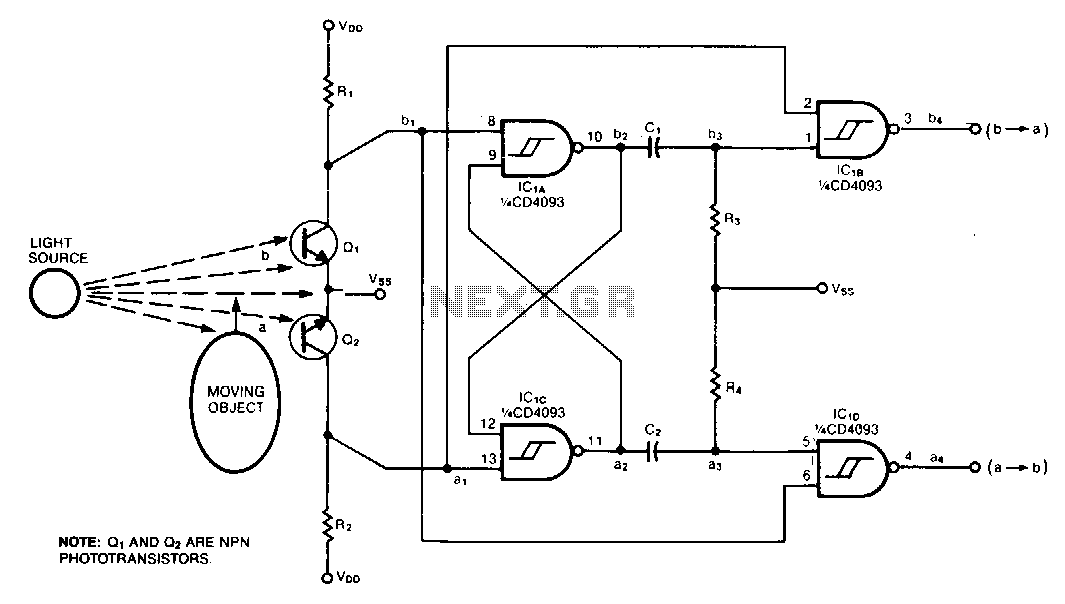
This circuit was designed to monitor the traffic of bumblebees entering and exiting the hive, distinguishing between a-to-b motion and b-to-b motion. When paired with an optical decoder, the circuit differentiates between clockwise and counterclockwise rotation, providing a resolution...
The circuit was constructed using a few components powered by a 9 V battery to sense the presence of bugs transmitting within the frequency modulation. The circuit design utilizes a 9 V battery as the primary power source, making it...
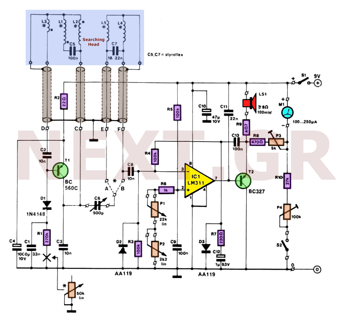
Metal detectors can be categorized based on their operational principles into three types: BFO (Beat Frequency Oscillator), TR/IB (Transmit-Induction/Balance), and PI (Pulsed Induction). Each method has its own set of advantages and disadvantages. An ideal metal detector, which does...