
Load detector Mains Switch

The circuit described functions as a master-slave power management system. It utilizes a low-value, high-wattage resistor (R1) to sense the current draw of the master device. When the master device is powered on, the current flowing through R1 generates a voltage drop that is detected by the operational amplifier (U1, an LM358N). The op-amp is configured as a comparator, which compares the voltage across R1 against a reference voltage set by resistors R2 and R6.
If the voltage across R1 exceeds the reference voltage, the output of the op-amp goes high, activating the NPN transistor (Q1, a 2N3904). This transistor acts as a switch that energizes the relay (K1), which in turn closes its contacts to power the slave devices. The relay is rated for 12VDC coil voltage and can handle AC loads up to 10A, allowing for multiple devices to be powered simultaneously.
Capacitors C1 and C3 (10µF) are used for power supply decoupling, ensuring stable operation of the op-amp by filtering out noise. Capacitor C2 (1µF) may serve a similar purpose or be involved in timing or stability for the comparator circuit. The diodes (D1, D2, D4 - 1N4004) provide rectification and protection against reverse voltage, while D3 (1N4744) serves as a Zener diode to maintain a stable reference voltage for the op-amp.
Resistors R3, R4, R5, R7 are involved in setting the gain and stability of the op-amp circuit. The SPST switch (S1) allows for manual bypassing of the automatic switching feature, providing a way to control the slave devices without needing to power the master device.
This circuit is designed for 120V mains operation, with provisions for modification for 240V by changing R2 and R6. Safety precautions are emphasized, as the circuit is not isolated from the mains, necessitating careful handling to avoid electrical hazards.This circuit will automatically switch on several mains-powered "slave" loads when a "master" load is turned on. For example, it will switch on the amplifier and CD player in a stereo system when the receiver is turned on.
It works by sensing the current draw of the "master" device through a low value high wattage resistor using a comparator. The output of that comparator then switches on the "slave" relay. The circuit can be built into a power bar, extension cord or power center to provide a convenient set of "smart" outlets that switch on when the master appliance is powered (turn on the computer monitor and the computer, printer and other peripherals come on as well).
C1, C3 2 10uF 35V Electrolytic Capacitor C2 1 1uF 35V Electrolytic Capacitor R1 1 0.1 Ohm 10W Resistor R2 1 27K 1/2W Resistor R3, R4 1 1K 1/4W Resistor R5 1 470K 1/4W Resistor R6 1 4.7K 1/2W Resistor R7 1 10K 1/4W Resistor D1, D2, D4 3 1N4004 Rectifier Diode D3 1 1N4744 15V 1 Watt Zener Diode U1 1 LM358N Dual Op Amp IC Q1 1 2N3904 NPN Transistor K1 1 Relay, 12VDC Coil, 120VAC 10A Contacts S1 1 SPST Switch 120AVC, 10A MISC 1 Board, Wire, Socket For U1, Case, Mains Plug, Socket This circuit is designed for 120V operation. For 240V operation, resistors R2 and R6 will need to be changed. A maximum of 5A can be used as the master unless the wattage of R1 is increased S1 provides a manual bypass switch.
THis circuit is not isolated from the mains supply. Because of this, you must exercise extreme caution when working around the circuit if it is plugged in. 🔗 External reference
Related Circuits
A simple test circuit designed for troubleshooting audio and radio equipment. It can inject a square wave signal rich in harmonics or be used with headphones as an audio tracer. A single-pole double-throw switch is utilized to toggle between...
This circuit is a differential analog switch circuit utilizing the FM1208 monolithic dual differential multiplexer. It is designed for applications where the on-resistance (RDS(ON)) must match closely. The RDS(ON) for the monolithic dual multiplexer exhibits better than 1% accuracy...

This design circuit is for a tone/frequency detector (decoder) that can detect the presence of a signal with a specific tone. The output of the circuit will be active if the signal matches the tone of an internal oscillator....
A simple circuit with which we have the possibility of opening and closing the RL1 contacts. It becomes active by touching a small metal surface. The status of RL1 is indicated by the LED D3. The supply voltage for...

This circuit switches a printer's USB connection from a PC to a laptop. The goal is to enable a laptop to use the printer occasionally. The circuit functions as a USB switch, allowing the user to select between two devices...
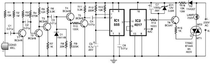
This 555 timer clap switch circuit electronic project is designed using common electronic components. The circuit operates from a distance of up to 10 meters from the microphone. The signal from the microphone is amplified by transistors T1, T2,...