
Alarm Digital Clock Schematic Diagram

The described circuit involves an I2C (Inter-Integrated Circuit) communication protocol, which utilizes two lines: SCL (Serial Clock Line) and SDA (Serial Data Line). The SCL line is responsible for clocking the data, while the SDA line carries the actual data being transmitted. In a typical I2C communication sequence, the master device initiates communication by setting the SCL line high, indicating that the SDA line is ready to transmit data.
When the SCL line is high, the SDA line must remain stable, ensuring that the data being transmitted is valid and legally binding. Any changes to the SDA line can only occur when the SCL line is low, which is a critical aspect of the I2C protocol. This timing ensures that the receiver can accurately read the data bits being sent.
Upon the successful reception of a byte of data, the receiver sends an acknowledgment (ACK) back to the sender. This is accomplished by the receiver pulling the SDA line low during the next clock pulse, which informs the sender that the data has been received correctly. If the sender does not receive an acknowledgment, it may retransmit the data or take other appropriate actions.
This communication protocol is widely used in various electronic devices, including sensors, microcontrollers, and peripheral devices, due to its simplicity and efficiency in multi-device communication. The I2C bus allows multiple devices to be connected to the same two lines, facilitating communication without requiring additional wiring for each device. The clock line (SCL) and data line (SDA) are typically pulled high by pull-up resistors, ensuring that the lines are in a known state when not actively driven by a device. This design is essential for reliable data transmission in digital circuits, particularly in applications such as alarm digital clocks, where precise timing and data integrity are crucial.after SCL is high at hand must be refusal chande voguish SDA line lone followed by the data is legally binding, the data loose change be supposed to be there made only as SCL is low. taking into account transfer of lone byte of data the reciever has to acknowledge the sender pro the winning reception.
for this the sender add up to the SDA line soa ring and reciever pulls down the SDA low, which tells the sender so as to data has reached safely. You are reading the Circuits of Alarm Digital Clock And this circuit permalink url it is 🔗 External reference
Related Circuits
The emergency driver unit includes a battery charger and electronic circuitry housed in a compact case. It features battery protection for emergency lighting against overcurrent and heat. Additionally, it has protection for the liquid crystal display (LCD) screen against...
1993 Jeep Grand Cherokee Horn System Wiring Diagram. The horn system in the 1993 Jeep Grand Cherokee is an essential component for vehicle safety and communication. The wiring diagram for this system provides a visual representation of the electrical connections...
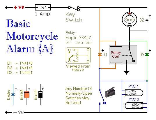
These are two easy to build relay-based alarms. You can use them to protect your motorcycle but they have many more applications. If you use relays with 6-volt coils, they'll protect your "Classic Bike". Both alarms are very small....
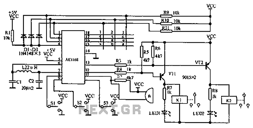
The circuit diagram represents an enhanced lock system, the AE1169, which is an upgrade of the AE1168 model. When the lock button is pressed, the AE1168 utilizes a keyboard scanning method to identify the corresponding button. Based on the...
This circuit is designed to drive a total of 42 LEDs, assuming a forward voltage of approximately 2.2V per LED and a forward current of around 21mA for adequate brightness. If the specifications of the LEDs differ significantly, modifications...
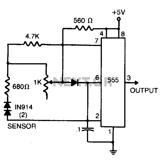
The sensor comprises two series-connected 1N914 diodes, which are part of the circuit of a 555 multivibrator. When wired as illustrated, the output pulse rate is proportional to the temperature of the diodes. This output is then fed into...