
Nicad Battery Charger

The charger circuit described operates by employing a BD140 transistor configured as a constant current source, which is essential for safely charging rechargeable batteries. The use of two 1N4148 diodes in series creates a stable voltage drop that is necessary for biasing the transistor's base. This arrangement ensures that the transistor operates within its linear region, allowing it to maintain a steady output current, which is critical in battery charging applications.
When the switch is closed, the circuit can deliver two different charging currents: 15mA for lower capacity batteries and 45mA for higher capacity batteries. This feature provides flexibility in charging various types of batteries, making the charger versatile for both 1.5V and 9V applications. The choice of a transformer with a 12V AC secondary rating at 0.5A is appropriate, as it provides sufficient power for the charging process while maintaining safety and efficiency.
The primary side of the transformer must be selected based on the regional voltage supply, either 220/240 volts for European systems or 120 volts AC for North American systems. This ensures that the transformer operates correctly within its specified voltage range, preventing overheating or failure.
Safety precautions are paramount when working with this circuit. The use of a voltmeter to check polarity before connecting the battery is crucial, as incorrect connections can lead to catastrophic failures, such as battery explosions. Nickel-cadmium batteries, in particular, are sensitive to improper handling, and caution should always be exercised during operation. By following these guidelines and understanding the circuit's functionality, users can effectively and safely charge their rechargeable batteries.This simple charger uses a single transistor as a constant current source. The voltage across the pair of 1N4148 diodes biases the base of the BD140 medium power transistor. The base - emitter voltage of the transistor and the forward voltage drop across the diodes are relatively stable. The charging current is approximately 15mA or 45mA with the switch closed. This suits most 1. 5V and 9V rechargeable batteries. The transformer should have a secondary rating of 12V ac at 0. 5amp, the primary should be 220/240volts for Europe or 120volts ac for North America. WARNING: Take care with this circuit. Use a voltmeter to observe correct polarity. Nicads can explode if short circuited or connected with the wrong polarity. 🔗 External reference
Related Circuits

An LM317 voltage regulator is configured as a constant-current source to supply a 50 mA charging current to S01-S06, which is an array of AA-cell battery holders. Each battery holder is connected in series with an LED and its...
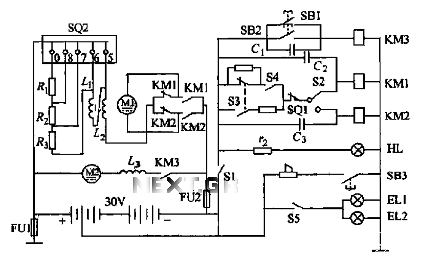
Battery forklifts are commonly used as stacking and handling tools in railway stations, docks, and warehouses. The battery shape and electrical control circuitry are depicted in the schematic. The system consists of batteries connected in series to form a...

The circuit is simple to assemble and install, and it notifies the user when the battery voltage drops below a predefined threshold set by R1, which is a 10,000-ohm potentiometer. It can signal through LED1 that the battery may...
This circuit provides an initial voltage of 2.5V per cell to quickly charge a car battery. The charging current decreases as the battery charges, and when the current drops to 180 mA, the charging circuit reduces the output voltage...
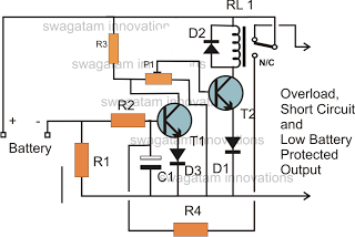
The battery voltage must pass through resistor R1 before reaching the output load. As a result, the current flowing through R1 is proportionately transformed into a voltage across it. When the battery voltage drops below a certain threshold, the...
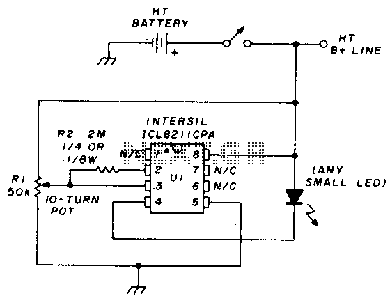
The precision voltage-monitor chip features a temperature-compensated voltage reference. Resistor R1 divides the battery voltage to align with the built-in reference voltage of IC1 (15 volts). When the voltage at pin 3 drops below 15 volts, pin 4 provides...