
Alternator Regulator Circuit

The alternator regulator circuit operates by employing a 3-transistor DC amplifier configuration, which effectively manages the voltage supplied to the alternator's field winding. In this design, one terminal of the field winding is connected to the +12V supply, while the other terminal is grounded, creating a pulled-up field system. This configuration allows for efficient control of the magnetic field generated by the alternator, which in turn regulates the output voltage and current to charge the battery and power the vehicle's electrical systems.
The circuit's ability to monitor the battery state is crucial for maintaining optimal performance. It incorporates a resistive voltage divider that samples the battery voltage. The output from this divider provides feedback to the transistor amplifier, enabling it to adjust the field voltage dynamically. When the battery voltage drops below a predefined threshold, the regulator increases the voltage at the field terminal, enhancing the magnetic field strength and boosting the alternator output. Conversely, if the battery voltage exceeds the desired level, the regulator reduces the field voltage, preventing overcharging and potential damage to the battery.
Overall, this alternator regulator design ensures efficient charging, prolongs battery life, and maintains the reliability of the vehicle's electrical system by continuously adapting to changing conditions. This alternator regulator uses a 3-transistor dc amplifier, and is designed for a pulled up field system, where one side of the alternate field returns to the +12-Vsupply, and the other end is pulled toward ground. The circuit monitors the state of the battery through a resistive divider and causes the voltage to change at the field terminal.
Related Circuits
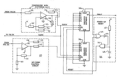
This motor overload circuit allows for short-term overdriving of a system, which is dependent on heat buildup. An overload detection circuit safeguards the motor against currents exceeding the rated current for specific exposure durations. The permissible exposure times are...

The TEA5551T monolithic integrated radio circuit can be utilized to design an AM radio receiver, intended for use as a portable radio receiver with headphones. The TEA5551T radio receiver circuit encompasses all necessary components for a complete AM receiver,...
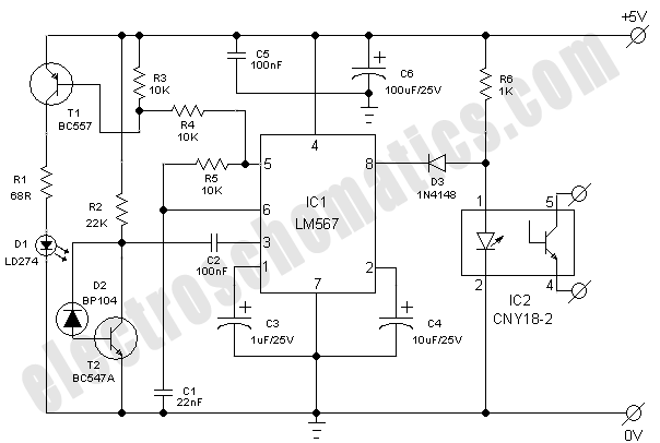
This simple and economical infrared model train detector circuit is designed specifically for hobbyists who want to incorporate a smart sensor to detect trains on their model railway track. The schematic diagram illustrates a straightforward configuration comprising an infrared...

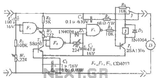
A simple dimmer circuit can be constructed using the CMOS ICs TT8486A and TT6061A, allowing control over the intensity of an incandescent lamp through a touch contact. This electronic touch dimmer can increase the brightness of incandescent lamps in...
This application note explains how the transfer function of most operational amplifier circuits can be derived through a straightforward process of nodal analysis. The transfer function of operational amplifier (op amp) circuits is a critical aspect for understanding their behavior...
The "R-h sampling circuit limit order" aims to reduce the sampling resistor. A DC voltage level can be positioned between the components. The circuit includes a line amplifier that allows for magnification adjustments and is designed to protect against...