
tea5551t am radio receiver circuit design electronic project

The TEA5551T circuit operates by receiving amplitude-modulated (AM) signals, which are then demodulated to extract the audio information. The integrated design simplifies the overall layout, reducing the number of external components required, which is particularly advantageous for portable applications. The dual AF amplifier enhances the audio output, ensuring that the sound quality is sufficient for headphone listening.
To construct the inductors L1, L2, and L3, specific winding techniques and core materials must be considered to achieve the desired inductance values. Typically, these inductors can be made using enameled copper wire wound around ferrite cores or air cores, depending on the frequency of operation and the design specifications. It is crucial to adhere to the specified number of turns and wire gauge to ensure optimal performance of the radio receiver.
The schematic of the TEA5551T AM radio receiver will include connections for the power supply, antenna input, and audio output to the headphones. Additionally, tuning capacitors may be employed to allow for frequency adjustment, enabling the user to select different AM stations. Proper grounding and shielding techniques should be implemented to minimize interference and improve reception quality.
In summary, the TEA5551T monolithic integrated circuit provides a compact and efficient solution for building an AM radio receiver, while the construction of inductors L1, L2, and L3 is essential for achieving the required inductance for optimal circuit performance.Using TEA5551T monolithic integrated radio circuit can be designed a AM radio receiver circuit which is designed for use as a portable radio receiver with headphones. The TEA5551T radio receiver circuit contains all is needed for a AM radio receiver circuit (a complete AM part and dual AF amplifier with low quiescent current).
Because in most cas e we don`t find to buy inductors you need to build the inductors L1, L2, L3. In the picture bellow you can see the construction data for these three inductors. 🔗 External reference
Related Circuits
The welder no-load power saver circuit consists of a current detection control circuit and a power saving control circuit, as illustrated in the accompanying chart. The current detection control circuit includes a current transformer (TA), a bridge rectifier (UR),...
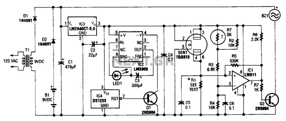
The gas sensor primarily consists of tin dioxide mounted on a ceramic substrate. The sensor's resistance changes based on the concentration of reducing gases present in the air. The depicted circuit is effective for detecting hazardous levels of combustible...

An AC mains operated single LED flasher circuit is constructed using the widely utilized CMOS timer chip TLC555. The entire circuit is powered directly from the 230VAC grid supply via a capacitive potential divider and associated components. This compact...

A pair of multi-range timers that provide timing periods extending up to 24 hours and beyond. Both timers are fundamentally identical, with the primary distinction being their relay behavior upon the completion of the timing cycle. Version 1 activates...
The diagram illustrates a human infrared remote sensing lamp circuit. It utilizes the trace infrared heat emitted by humans to control the lamp's operation, allowing it to turn on or off remotely. This human infrared remote sensing lamp features...
R1, D3, and C1 are optional components. Only one LED is necessary. If the LED does not illuminate, try reversing its polarity. Initially, a single 555 circuit was used, but high current consumption was a concern. Additionally, the R5...