
overcurrent detection circuit

This motor overload protection circuit is designed to ensure the reliable operation of a DC motor by monitoring the armature current and preventing damage due to excessive current conditions. The circuit employs two current sensors, each calibrated to detect specific overload levels: one at 100% of the rated current and another at 150%. When the current exceeds these thresholds, the sensors generate signals that feed into a pulse-generating circuit. This circuit is crucial for determining the duration and frequency of the overload condition, as it produces pulses that are counted by cascaded counters.
The integration of an integrator circuit allows for accurate timing and control of the pulse generation. The capacitor within the integrator must be discharged before a new pulse can be generated, ensuring that the circuit accurately reflects the current condition without introducing delays. The comparator's role in discharging the capacitor just prior to pulse generation is a significant enhancement, as it mitigates potential timing issues that could affect the responsiveness of the overload detection.
When the counters reach a predetermined count, a fault signal is generated, which is relayed to a fault flip-flop. This flip-flop is integral to the safety mechanism of the circuit, as it activates switching circuitry that deenergizes the control relay, effectively disconnecting the motor from its power source. This disconnection is crucial for preventing damage to the motor and ensuring safe operation under overload conditions.
The design's flexibility in response characteristics is a notable improvement over traditional overload protection circuits. By allowing for a two-segment response curve, engineers can tailor the circuit's sensitivity and response time to suit specific applications, enhancing its effectiveness in protecting motors from varying overload conditions. This adaptability makes the circuit suitable for a wide range of industrial and commercial applications where motor protection is critical.This motor overload circuit does not simply disallow overloading since it is permissible to overdrive a system but only if it is done for a short time (typically dependent on heat buildup). An overload detection circuit protects a motor against currents above rated current that persist for certain exposure times.
The allowable exposure times are i nversely related to the degree of overload current. The circuit has two overload current sensors with two respective overload thresholds. These are both connected to a pulse generating circuit and the pulse rate is accelerated when the second overload threshold is reached. The pulse generating circuit couples pulses to a pair of cascaded counters which generate a fault signal when a predetermined count is reached.
The pulse generating circuit includes an integrator with a capacitor that must be discharged, before another pulse can be generated. The pulse generating circuit includes a comparator which operates a switch to discharge the capacitor shortly before coupling each pulse to the counters, to prevent a delay that would otherwise occur between signals from the integrator circuit.
The design relates to a first improvement of multiple current-sensing circuits for an overcurrent protection device which are responsive in different degrees to various overcurrent conditions. Whereas the prior art provided a typical inverse response characteristic of overload trip time as a function of overcurrent, the present design provides a two-segment response characteistic in which the breakpoint between the segments and the shape of the response curve in the second segment can be controlled by the selection of components for the invented circuit.
The design also relates to a second improvement in overcurrent detection devices of the type using an integrator circuit to generate pulses to indicate overcurrent. The design provides an integrator reset circuit which is triggered by the leading edge of a pulse before the trailing edge is coupled to the overload pulse counters to advance the counters by one count.
Referring to FIG. 1, overload current is detected in the operation of a DC electrical motor 10 having an armature 11 and a field winding 12. The motor is energized from a power source 13 through a DC motor drive control 14 in which the overload detection device 15 seen above the dashed line in FIG.
1 can be utilized. The motor drive control 14 includes current transformers 16 which sense armature current on the AC side of the motor drive 14. This current is rectified in the motor drive control 14 to provide a signal (ABS. IA) representing the magnitude of direct current supplied to the armature 11. This signal is coupled to the overload detection device 15 and more specifically, to circuits 21 and 22 to be described below.
The output of the overload detection device 15 is a FAULT signal which is coupled to a fault flip-flop 17. The fault flip-flop 17 in turn couples a signal to switching circuitry 20 to deenergize a coil 18 in a control relay (CR).
The deenergizing of the coil 18 opens a pair of associated contacts 19 to disconnect the motor 10 from the line supplying DC power to it. The coil 18 of the control relay is connected between a voltage source (+V) and ground through the switching circuitry (SW) 20, which is operated to energize the coil 18 and close the contacts 19 during start up of the motor 10.
An overview of the operation of the overcurrent detection circuit 15 will now be described. As seen in FIG. 1, when the magnitude of ABS. IA indicates a current in excess of 100% of rated current for the motor armature 10, this condition will be sensed by 100% RATED CURRENT SENSOR circuit 21. When the magnitude of ABS. IA indicates a current in excess of 150% of rated armature current, this connection will be sensed by a 150% RATED CURRENT SENSOR circuit 22.
The output of the two sensor circuits 21 and 22 is summed at a summin 🔗 External reference
Related Circuits

This is a simple circuit design for a video transmitter capable of radiating signals up to 50 meters. The video transmitter can be connected to a camera as a source and allows viewing on a VHF channel analog television....

Circuit characteristics: A simple phase shift range of 180 degrees, with a practical range of 170 degrees. The circuit is influenced by temperature and is suitable for small power applications in less demanding situations. The circuit operates by utilizing a...
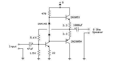
This weblog focuses on electronic circuit schematics, PCB design, DIY kits, and electronic project diagrams. The following describes a small audio amplifier, similar to those found in medium-sized transistor radios. The input stage is biased to ensure equal power...

Some good inverter circuits I found oscillate at approximately 50 to 60 Hz. They are likely capable of handling up to two amps; any more than that will cause them to automatically shut off. If there are questions, please...
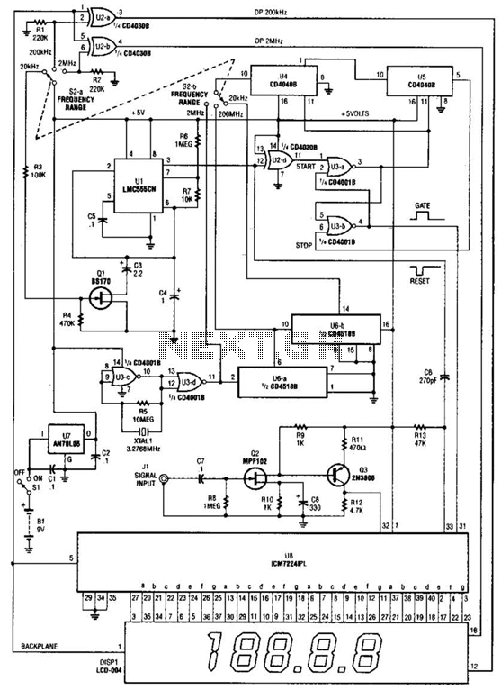
This is a schematic and block diagram of a 2-MHz frequency counter. It utilizes an LSI counter/display driver, an LCD readout, and several logic chips for timebase and timing pulse circuitry. Q2 and Q3 serve as a signal (input)...
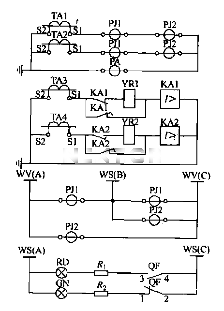
Expanding schematic circuit for the secondary circuit of high-voltage lines. The schematic circuit for the secondary circuit of high-voltage lines is designed to enhance the distribution and management of electrical power in high-voltage systems. This circuit typically includes components...