
AM base circuit

The circuit operates within the framework of amplitude modulation, where the information signal modifies the amplitude of a high-frequency carrier wave. The high-frequency bypass capacitor (C) is crucial for stabilizing the circuit by preventing high-frequency noise from affecting the performance of the AM signal. It allows AC signals to pass while blocking DC, ensuring that the modulation process remains unaffected by fluctuations in the power supply.
Transformers T1 and T2 are integral to the circuit, facilitating the transfer of energy between different stages while maintaining the integrity of the high-frequency signals. These transformers are designed to efficiently couple the signal at the desired carrier frequency, ensuring minimal loss and optimal performance.
The LC resonant circuit is tuned to the carrier frequency, enabling selective amplification of the desired signal while filtering out unwanted frequencies. The passband of 2Fr indicates the range of frequencies around the carrier frequency that the circuit can effectively process, allowing for the transmission of modulated signals with minimal distortion.
For the detection of the modulated signal, a low-pass filter is employed to isolate the baseband signal from the high-frequency components. The square-diode detector operates by rectifying the incoming modulated signal, allowing for the recovery of the original information signal. The term "small signal square-detector" highlights the circuit's capability to handle low-amplitude signals, which is essential in applications where the input signal is weak, such as in communication systems and radio receivers. This design emphasizes the importance of precision in signal processing, ensuring reliable detection and reproduction of the transmitted information.AM base for small-signal amplitude modulation, the circuit as shown C is a high frequency bypass capacitor. Tl, T2 is a high frequency transformer, LC resonant circuit at the carrier frequency , passband is 2Fr. . Change, and then implement the detector through a low-pass filter, this detection method called square-diode detector.
Due to the small high-frequency input signal amplitude, fork called small signal square-detector.
Related Circuits
It is entirely logical that low-cost miniature microcontrollers have fewer pins than their larger counterparts, sometimes too few. Consideration has been given to how to economize on pins by making them perform the work of several. It was noted...
The FM302E-I-type FM transmitter exciter is manufactured by NEC Corporation, Japan, and features a 1210 motherboard. It utilizes direct frequency modulation of the carrier signal, employing phase-locked frequency stabilization and frequency synthesis techniques. The front power amplifier is based...

This circuit design generates a stable 1 kHz sine wave using an inverted Wien bridge configuration with components C1-R3 and C2-R4. It offers a variable output, low distortion, and low output impedance to ensure good overload capability. The circuit...
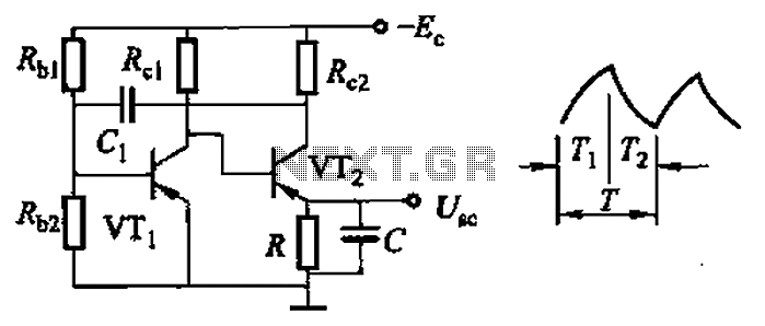
Common non-sinusoidal oscillator circuit, waveform and frequency formula - sawtooth oscillator - use multivibrator. The sawtooth oscillator is a type of non-sinusoidal waveform generator that produces a triangular or sawtooth-shaped output signal. This oscillator is commonly utilized in various applications,...
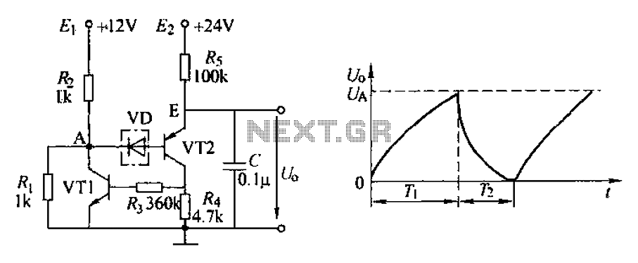
The application circuit depicted is a complementary sawtooth generator. In the schematic, VT1 is the transistor with a base current limiting resistor, which prevents excessive base current flow through the crystal tube. The resistor R4 acts as a bleeder...
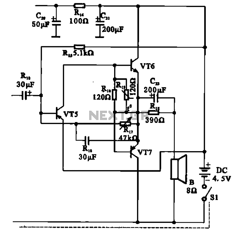
The transistor radio features a common output transformerless (OTL) power amplifier circuit. The VT5 component serves as the bias resistor for the driver stage. VT6 and VT7 form a complementary symmetry configuration, with VT6 being a germanium NPN transistor...