
Common non-sinusoidal oscillator circuit waveform sawtooth oscillator use multivibrator

The sawtooth oscillator is a type of non-sinusoidal waveform generator that produces a triangular or sawtooth-shaped output signal. This oscillator is commonly utilized in various applications, including audio synthesis, signal processing, and timing circuits. The fundamental operation of a sawtooth oscillator involves charging and discharging a capacitor through a resistor, which results in a linear ramp-up of voltage followed by a rapid drop to the initial voltage level.
The circuit typically employs a multivibrator configuration, often using operational amplifiers or transistors. In a standard implementation, a capacitor is charged through a resistor until it reaches a predetermined threshold voltage, at which point the output switches state, causing the capacitor to discharge rapidly. The frequency of the sawtooth waveform can be determined by the values of the resistor and capacitor according to the formula:
\[ f = \frac{1}{T} = \frac{1}{R \cdot C \cdot \ln(\frac{V_{max}}{V_{min}})} \]
where \( f \) is the frequency, \( R \) is the resistance, \( C \) is the capacitance, \( V_{max} \) is the maximum voltage, and \( V_{min} \) is the minimum voltage.
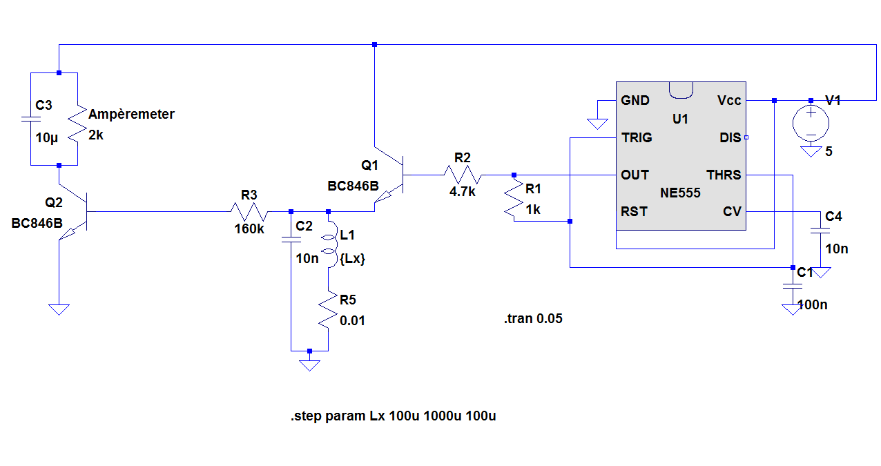
For practical implementation, the circuit can be designed using a 555 timer in astable mode or with a combination of transistors configured as a Schmitt trigger. In both cases, careful selection of resistor and capacitor values is crucial for achieving the desired frequency and waveform characteristics. The output can be further processed or filtered to meet specific application requirements, such as generating audio signals or controlling other electronic components.
Overall, the sawtooth oscillator is a versatile circuit that can be adapted for various electronic applications by modifying component values and configurations to tailor its performance. Common non-sinusoidal oscillator circuit, waveform and frequency formula - sawtooth oscillator - use multivibrator
Related Circuits
C1 takes the DC-decoupled voltage from the microphone, amplifies it via Q1, then C2 decouples it again. R6 and C3 form a low-pass filter, but once the signal reaches Q2, the circuit accomplishes frequency modulation. The frequency deviation is...
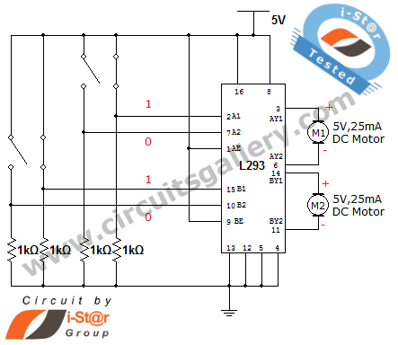
How can a DC motor be rotated in clockwise and counterclockwise directions? This is a common question posed by many robotics beginners. DC motor driver circuits are essential components in robotics workshops. The L293D IC is frequently utilized for...
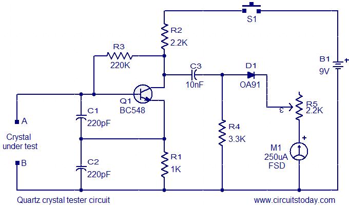
This is a straightforward and cost-effective circuit designed for testing quartz crystals. A Colpitts oscillator is employed using transistor T1. When the crystal is connected between terminals A and B, the circuit generates high-frequency oscillations. These oscillations will only...
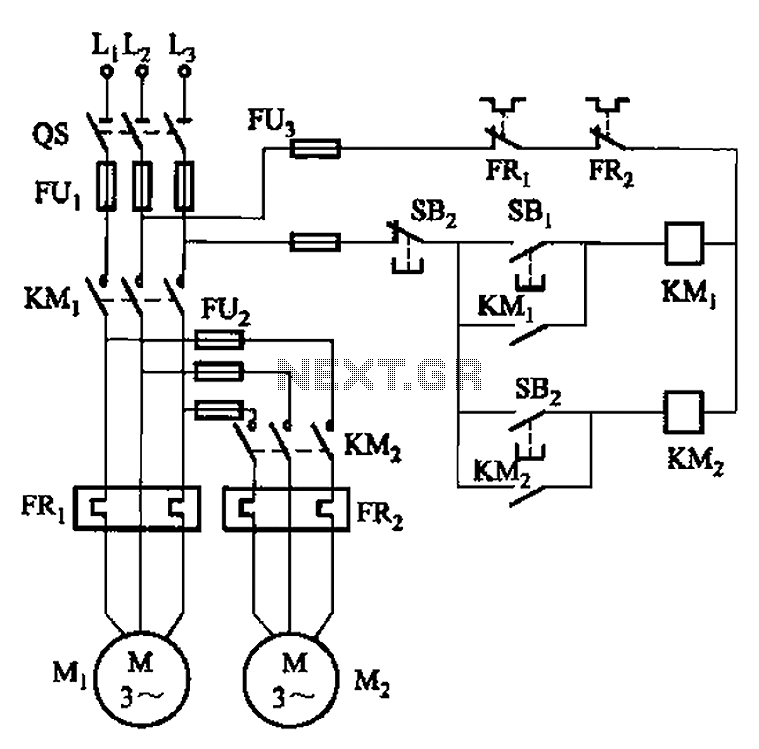
The circuit illustrated in Figure 3-83 demonstrates that the contactor KMi is activated only after it is pulled, which indicates that the motor Mi has started for the first time. Following this, the contactor KM2 is then activated, indicating...
Sinusoidal pulse width modulation (SPWM) has been discussed in terms of generating a sine table, implementing it, and practically generating SPWM signals with example code. Additionally, feedback implementation through simple sine table manipulation with a table pointer, as opposed...

The MK484 AM radio circuit offers a comprehensive solution that includes an RF amplifier, detection, and automatic gain control (AGC) circuit. It requires only a few external components to achieve a high-quality AM tuner. The circuit features an input...