
Video cable driven by the MAX4104 4105 4304 4305 s an enlarged schematic

The MAX4104/4105/4304/4305 video cable driver amplifier circuit is engineered to enhance the transmission of video signals over coaxial cables. This is crucial for applications where signal integrity is paramount, such as in broadcasting or high-definition video systems. The design ensures that the output impedance of the amplifier is precisely aligned with the characteristic impedance of the coaxial cable, typically 75 ohms. This matching is essential to minimize signal reflections that can degrade the quality of the transmitted video signal.
The operational characteristics of the MAX4104/4105/4304/4305 amplifiers include high bandwidth and low distortion, making them suitable for high-frequency video applications. The configuration allows for the amplification of the video signal without introducing significant noise or distortion, which is critical for maintaining the clarity and fidelity of the video being transmitted.
In practical implementation, the circuit may include additional components such as capacitors for AC coupling, resistors for biasing, and possibly inductors for filtering, depending on the specific requirements of the application. Proper layout and grounding techniques are also essential to prevent interference and ensure optimal performance.
Overall, the MAX4104/4105/4304/4305 video cable driver amplifier circuit represents a robust solution for high-quality video signal transmission, leveraging the capabilities of the MAX series amplifiers to achieve superior performance in coaxial cable applications. As shown in FIG grounds MAX4104/4105/4304/4305 video cable driver amplifier circuit configured. MAX4104/4105/4304/4305 as a coaxial transmission line suitable for amplifying vi deo signals, for the transmission of the reflection minimum, to obtain the maximum power load, the output impedance of the amplifier is selected equal to the terminating impedance of the transmission line characteristic impedance (75 ). In this circuit, MAX4104/4105/4304/4305 interlocutory amplification, after the cable input video signal amplifier output, continue transmitted by the cable.
Related Circuits
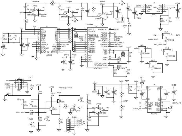
The circuit includes an ATmega88 as the main controller, an AD9280 ADC, an LM6134 high-speed quad op-amp, an LM1881 video sync separator, a 74HC4066 as a simple analog switch, and an RS-232 level converter. The LM1881 video sync separator...
This schematic has been developed as an exercise to learn about amplifiers. There are several aspects that require clarification and further understanding. The schematic in question likely involves a basic amplifier circuit, which may include components such as resistors, capacitors,...
This simple cable tester can be used to check two-wire cables such as coaxial cables, telephone cables, audio cables, and others. The circuit is powered by a 9V battery. To operate, plug in the cable and press the "TEST"...
In the presence of combustible gas, the conductance of the TGS308 gas sensor increases, causing the voltage at the potentiometer RP1 slide point to rise from a normal 3V RMS to 20V. This elevated voltage is applied to transistor...
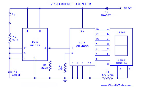
A simple seven-segment counter circuit with an LED display. This counter circuit diagram is designed using the IC CD 4033 as a counter, a 555 Timer IC, and a seven-segment LED display LT 543. The seven-segment counter circuit utilizes the...
The circuit below requires a double pole, double throw relay in conjunction with a single transistor to allow toggling the relay with a momentary push button. One set of relay contacts is used to control the load, while the...