
TV Transmitter circuit diagram (VHF)
")
The TV transmitter circuit described is designed to operate effectively within a range of frequencies, allowing for versatile applications. The choice of the BC 108 transistor is significant due to its favorable characteristics for RF applications; however, alternatives like the BC337, 2N2222, and BC546 can also be employed without compromising performance. This flexibility in component selection aids in accessibility for builders who may not have the original transistor on hand.
The inductor L1 plays a crucial role in determining the operating frequency of the transmitter. The winding specifications are tailored to achieve specific frequency ranges: 6 turns for the lower band (60 - 80 MHz), 4 turns for the mid-band (150 - 180 MHz), and 2 turns for the upper band (180 - 200 MHz). The use of #24 enameled wire for winding ensures adequate inductance while maintaining a manageable size for the air former, which is essential for effective signal transmission.
The circuit's design emphasizes simplicity and functionality, making it suitable for hobbyists and those interested in exploring RF transmission. Proper assembly and tuning of the circuit will yield optimal performance, allowing users to transmit signals effectively over the stated distances. Additionally, the invitation for others to contribute their circuit designs fosters a collaborative environment, promoting knowledge sharing within the electronics community.Most of people ask TV transmitters. So Today I`m going to give you a very useful circuit diagram. By using this circuit you can send your signals 75m to 100m. This circuit diagram is not my own circuit one of my friends gave me this. I suppose you guys also can send your own circuit diagrams for us. Then we can publish them through our website. Here The y have used common transistor BC 108 If you are unable to find this transistor you can use equal transistors like Bc337 2n2222 Bc 546 # To make L1 wound 6 turns of #24 enameled wire on a 10mm air former for frequency 60 - 80 MHz For 150 - 180 MHz wound 4 turns and for 180 - 200MHz wound 2 turns. 🔗 External reference
Related Circuits
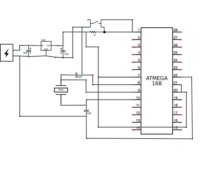
ATMega168 or ATMega328 microcontroller chip with Arduino bootloader (the one on your Arduino can be used temporarily) costs between $4.00 and $5.50. It is advisable to purchase an unbootloaded chip from Mouser for a lower price or a bootloaded...
This is a voltage doubling circuit built using the well-known timer IC 555. The circuit is straightforward and easy to construct. The construction is not critical. Rectifier diodes should be ultrafast (such as UF4004 or similar), or 1N4148 signal...

The required output from the inverter is 220/230V at 60Hz, with an output power of 1000VA. The first circuit represents a basic commercial UPS design, providing a constant regulated 5V output and an unregulated 12V supply. Upon failure of...

The 78W series voltage regulators are designed to handle an input voltage of approximately 35V, while the 24V type can withstand up to 40V. It should be noted that these regulators will not operate effectively with a significant input-output...
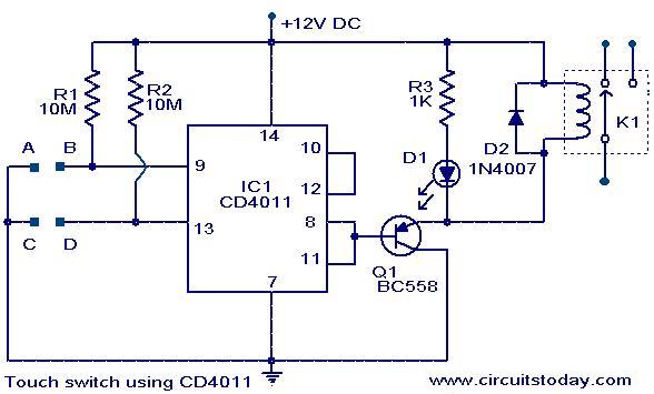
The following circuit illustrates a Touch Switch Circuit Diagram. This circuit is based on the CD4011 IC. Features include R1 and R2, which are the logic gates of the circuit. The Touch Switch Circuit utilizes the CD4011 integrated circuit, which...

The simple pulse width modulation circuit is illustrated in the figure. It utilizes an operational amplifier to create a multivibrator, resulting in a symmetrical oscillation output signal with a duty cycle of 50%. By adjusting the external threshold voltage,...