
Fan motor starting circuit diagram

The system control requirements aim to mitigate the starting load during the startup of the centrifugal fan. This can be achieved through a star-delta conversion method, which reduces the starting current along with safety interlock control measures. The main circuit of the fan motor starter is depicted in a referenced figure. In this configuration, contactors KM1 and KM2 are connected, while KM3 remains disconnected when the fan motor is in a star connection. When KM2 and KM3 are energized, and KM1 is off, the fan motor coils are switched to a delta connection, with interlocking between KM1 and KM3.
The selection of the PLC and the definition of the I/O system are based on a company's specifications, utilizing an OMRON type PLC for control. The I/O addresses are organized in a designated allocation table.
To enhance the operational reliability and efficiency of the high-pressure centrifugal fan system, the proposed PLC-based control strategy incorporates several key elements. The star-delta starter configuration allows for a reduction in the initial starting current, which minimizes stress on both the electrical components and the mechanical structure of the fan. Interlocking mechanisms between contactors KM1, KM2, and KM3 ensure that the transition between star and delta configurations occurs safely and without risk of short circuits or overloads.
In addition, the PLC provides a flexible platform for integrating various sensors and feedback mechanisms that can monitor the fan's operational parameters, such as temperature, vibration, and current draw. This data can be utilized for real-time adjustments to the fan's operation, ensuring optimal performance and preemptive maintenance alerts. The PLC's programmable nature allows for the implementation of complex control algorithms, including soft-start features and automatic fault detection, further enhancing the system's reliability.
The I/O allocation table for the PLC should be designed to accommodate all necessary inputs and outputs, including those for motor control, safety interlocks, and monitoring sensors. Each input and output should be clearly defined to facilitate troubleshooting and maintenance. Proper labeling and documentation of the control system will ensure that operators can efficiently manage the fan's operations and respond to any issues that may arise.
Overall, the integration of a PLC for the control of high-pressure centrifugal fans represents a significant advancement over traditional methods, providing improved reliability, flexibility, and safety in fan operation.Fan power equipment traditional control methods is through manual or relay control, there is the problem of poor reliability and flexibility. For example, the motor capacity at large, it takes a long time there is a starting, starting current dog, operational safety and poor reliability. To do this, we need more measures to achieve automatic control of high pressure centrifugal fan, and ensure the safe operation of the system.
This example discussed PLC for control of high pressure centrifugal fan problem. (1) system control requirements in order to solve these problems, we need to reduce the starting load at startup centrifugal fan, through a star delta conversion method to reduce the starting current, safety interlock control measures. Fan motor starter main circuit shown in Figure 26-21. Wherein the contactor KM1, KM2 connected, when KM3 disconnected fan motor is star-connected coils; KM2, KM3 contactor energized, KM1 off, the fan motor coil triangular link} KM1, KM3 should interlock.
(2) PLC selection and I/O system is defined by a companys coMl OMROM type PLC control. PL.C of I/O to the address allocation table
Related Circuits
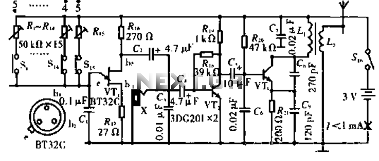
The circuit operates with VT3 and associated components arranged as a common-base capacitance feedback oscillation circuit. The oscillation frequency is set by capacitors C8, C9, and inductor L1. VT2 serves as a voltage amplification stage that reinjects the audio...
Stepper motors are a frequently discussed topic. This circuit converts a clock signal from a square wave generator into signals that have a 90-degree phase difference, which are necessary for driving the stepper motor windings. The trade-off for this...
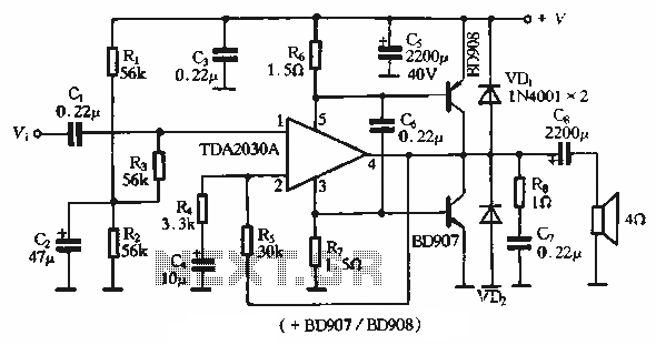
The rDA2030A TDA2030 is an enhanced version of the original product, with a maximum working voltage increased to 18V and a maximum output power of 18W. Additionally, harmonic distortion has been significantly reduced. The application circuit is illustrated. The rDA2030A...
This is a very simple circuit utilizing a 555 timer IC to generate a square wave of frequency that can be adjusted by a potentiometer. With values given, the frequency can be adjusted from a few Hz to several...
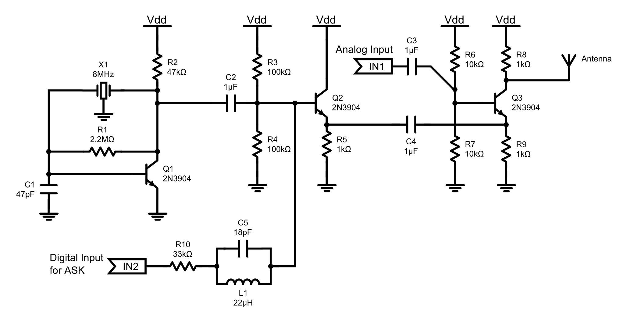
This is an 8MHz amplitude modulated (AM) radio transmitter designed primarily for practical applications and as an educational exercise in electronics. The objective was to create a simple radio transceiver that could be used in future projects requiring basic...
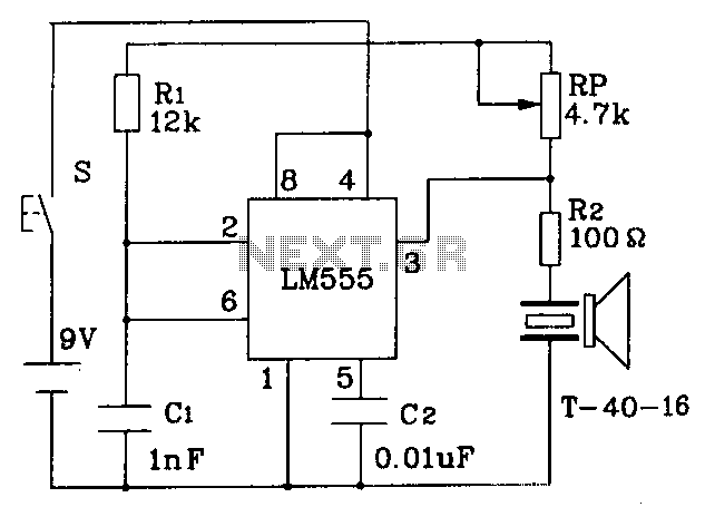
The circuit operates at a distance of 3 feet from the oscillating pulse output of a 555 timer generating a 40kHz signal, driving a T-40-16 transducer to emit ultrasonic signals at the same frequency. The circuit is powered by...