
Since a power charger circuit

A schematic for a bidirectional motor control circuit typically includes several key components: a multivibrator circuit, a motor driver, and a potentiometer for user input. The multivibrator generates a pulse-width modulation (PWM) signal, which is essential for controlling the speed and direction of the motor. The duty cycle of this PWM signal can be varied by adjusting the potentiometer, allowing for fine-tuned control over the motor's operation.
The motor driver, often implemented using an H-bridge configuration, enables the motor to rotate in both directions. The H-bridge consists of four switches (transistors or MOSFETs) that can be activated in pairs to reverse the polarity of the voltage applied to the motor. This arrangement allows the motor to be driven forward or backward by changing the state of the switches based on the PWM signal from the multivibrator.
In the circuit, when the potentiometer is centered, the multivibrator produces a symmetrical waveform, resulting in no net movement of the motor. Adjusting the potentiometer to one side increases the duty cycle of the PWM signal, which in turn increases the average voltage supplied to the motor, causing it to rotate in one direction. Conversely, moving the potentiometer to the opposite side decreases the duty cycle, reversing the motor's rotation.
The inclusion of feedback mechanisms, such as limit switches or encoders, can enhance the functionality of this circuit by providing position feedback to the control system, allowing for precise control of the motor's movement. Overall, this bidirectional control circuit is a versatile solution for applications requiring adjustable motor speed and direction. Bidirectional Control J 7 cases referred to the motor is to increase the degree I had a bit-what is to be achieved. iL Sweet Road 1-62 Figure 1 shows, the motor monkeys move J discernible star only 1.29310. It may be in either direction of the Zhu Bu j current 1A. The use of a variable duty cycle of the multivibrator that jil realization of construction and control direction. Located in the heart of towel when the potential of clamor, the oscillation waveform symmetry, when the motor is stopped when the potentiometer slide to one side.
Will be in the direction corresponding to the given partial giant, the motor is rotated.
Related Circuits
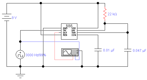
The 1-megohm resistor protects the FET from potential damage caused by accidental sparks to its gate lead. The circuit functions adequately without this resistor; however, it is advised not to intentionally apply a charge to the gate wire using...
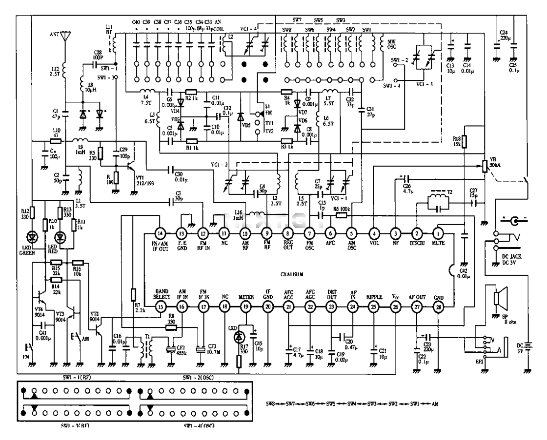
Desheng 1012 is a 12-band radio circuit diagram that covers FM, MW, SW, and TV sound frequencies. The Desheng 1012 radio circuit is designed to receive a wide range of frequencies across multiple bands, including FM (Frequency Modulation), MW...
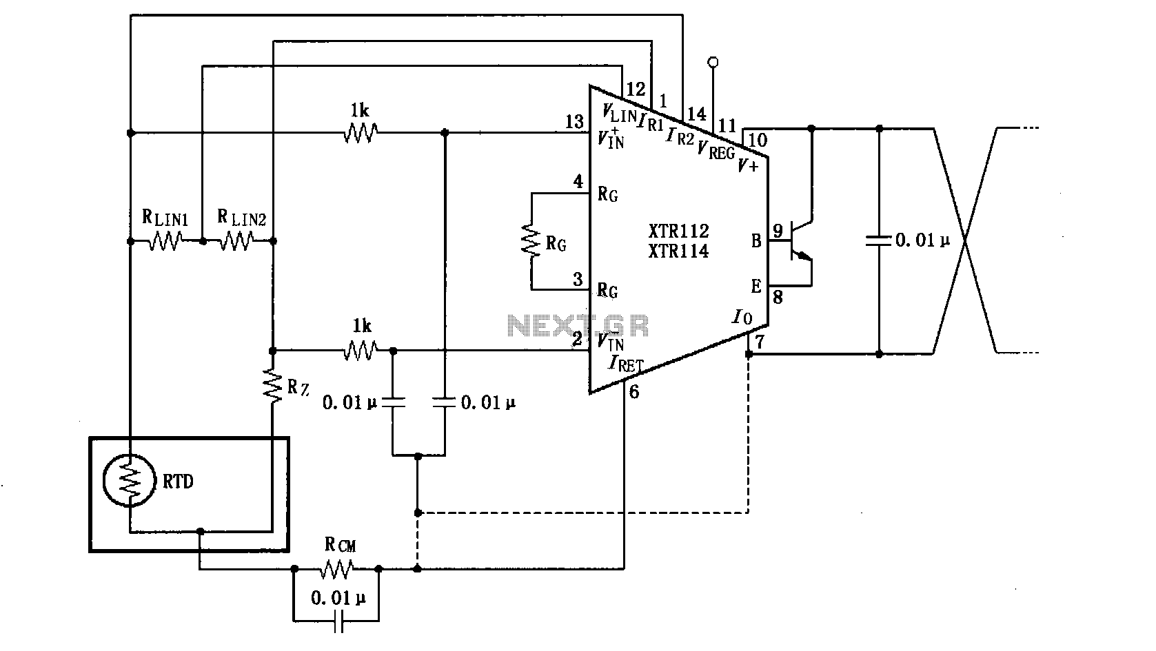
The length of the transmission wire in a current loop circuit can introduce radio frequency (RF) interference. This RF energy may lead to input errors in sensitive devices such as the XT112/114, causing instability in loop current or input...
The standard assumption is that the phase shift sections operate independently. According to the equation provided, the loop phase shift reaches -180 degrees when the phase shift of each section is 60 degrees. This condition is met when ω...
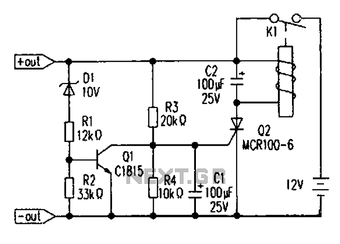
Battery discharge leads to plate acidification, negatively impacting the battery's lifespan. To address this issue, a specialized micro-power battery over-discharge protection circuit has been designed. The circuit features a very low detection current (1.1 mA). Once the protection circuit...
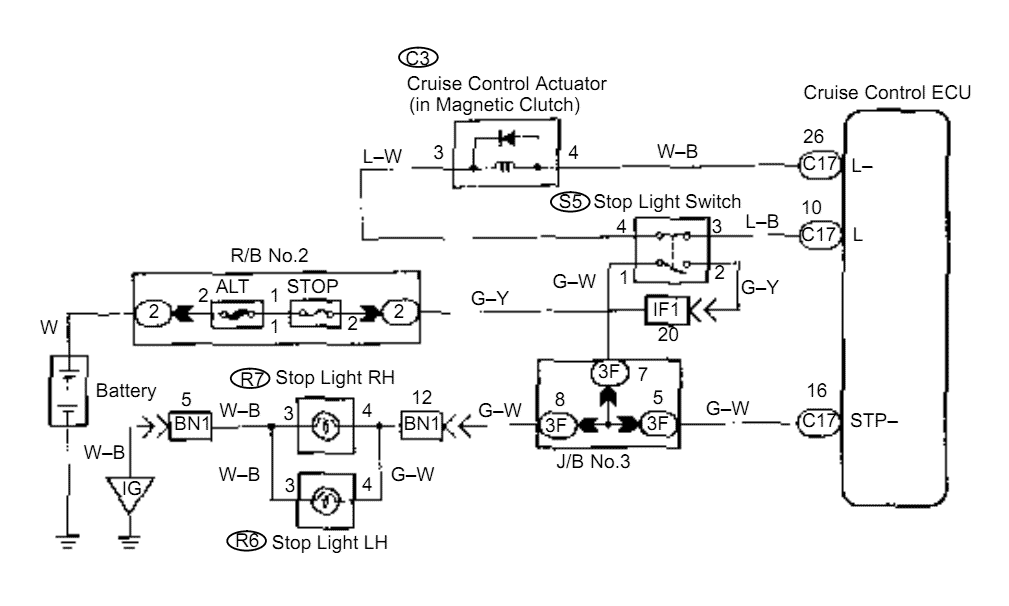
When the brake pedal is depressed, battery positive voltage normally applies through the STOP fuse and stop light switch to terminal STP of the ECU, and the ECU turns the cruise control off. A failsafe function is provided so...