
AM/cw 10-meter band transmitter

The described project involves constructing a low-power AM broadcasting circuit that utilizes a crystal oscillator integrated circuit (IC) and a collector modulated AM oscillator. The crystal oscillator provides a stable frequency source, essential for ensuring consistent transmission quality. The collector modulated AM oscillator serves to modulate the audio signal from the microphone onto the carrier frequency generated by the crystal oscillator.
To interface the circuit with an audio source, it is crucial to use an amplified microphone. This is due to the requirement of a minimum input voltage of approximately 100 to 200 mV for proper operation. If an amplified microphone is not available, an alternative approach involves incorporating a low-frequency (LF) preamplifier stage using a single transistor. This preamp stage can boost the microphone signal to the necessary levels, enabling direct connection to the oscillator circuit.
The design allows the broadcasted signal to be received by standard AM radio receivers, demonstrating the fundamental principles of amplitude modulation. While the circuit's simplicity contrasts with the more complex designs found in commercial AM radio stations, it effectively illustrates the basic concepts of RF transmission and reception. The circuit's performance can be further enhanced by optimizing component values and ensuring proper layout to minimize interference and signal loss.In this project, you will make a simple low-power broadcast-type circuit, using a crystal oscillator integrated circuit and an a collector modulated AM oscillator. You can connect the circuit to the an amplified microphone (no amplified microphone has a to low output voltage to work.
at least 100...200mv is needed). You could also add a LF preamp stage of one transistor to allow connecting a microphone directly. You`ll see that you can receive the signal through the air with almost any AM radio receiver. Although the circuits used in radio stations for AM receiving are far more complicated, this nevertheless gives a basic idea of the concept behind a princip 🔗 External reference
Related Circuits
This circuit is a highly stable, harmonic-free, long-range FM transmitter designed to operate within FM frequencies between 88 and 108 MHz. It is capable of covering a range of up to 5 kilometers. The circuit features a stable oscillator...
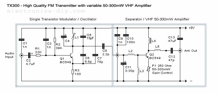
50-300mW FM Transmitter with TX300 Electronic Circuit Schematic Wiring Diagram. The FM transmitter circuit is designed to operate within a power range of 50 to 300 milliwatts, making it suitable for various applications such as amateur radio broadcasting and low-power...
The range of this transmitter is approximately 50 feet with a short whip antenna. The tone generator consists of a unijunction transistor (Q1) along with resistors R1, R2, R3, and capacitor C2. Transistor Q1 operates by pulsing on and...
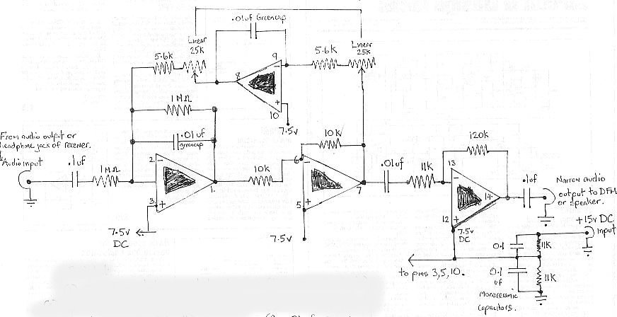
The audio bandpass filter described is beneficial for amplifying and filtering weak AM TV video carriers. For instance, a digital frequency audio multimeter (DFM) may lack sufficient input sensitivity for measuring extremely weak single sideband (SSB) TV video audio...

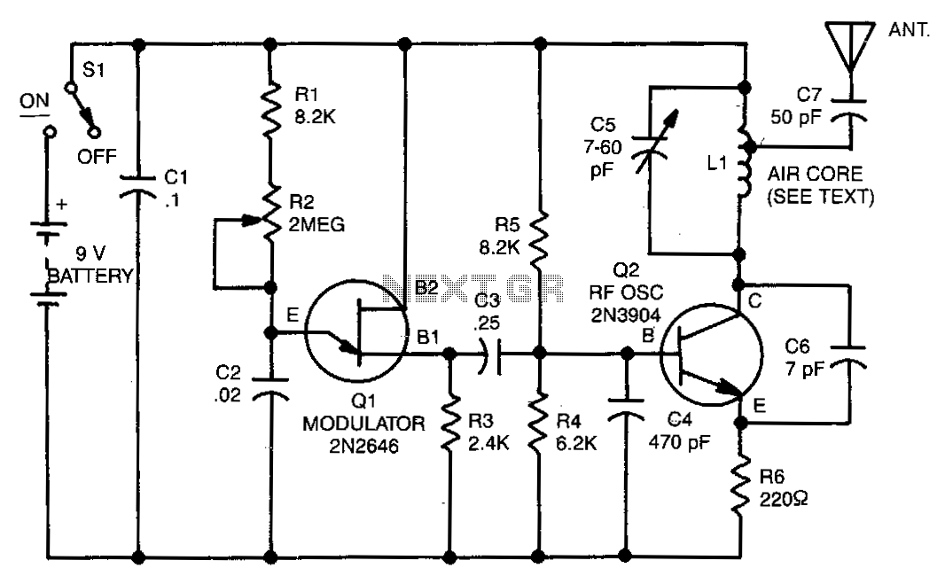
This is a mini FM transmitter powered by two transistors and designed by Tony van Roon. This compact transmitter is straightforward to assemble, and its signals can be received on any standard FM radio. It has a range of...
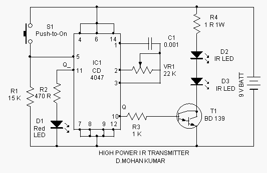
This infrared transmitter is capable of activating IR-based switching circuits from a distance of 10 meters or more. It features a high-power IR transmitter that drives two infrared LEDs. The infrared transmitter circuit is designed for remote activation of devices...