
Mini FM Transmitter

The mini FM transmitter described is a simple yet effective device for short-range audio broadcasting. The design, based on two transistors, allows for a compact and efficient layout, making it suitable for various applications, particularly in educational environments. The operational voltage range of 1.5 to 3 volts indicates that the transmitter can be powered by standard batteries, enhancing its portability and ease of use.
The circuit's construction involves a minimal number of components, which contributes to its low cost and ease of assembly. The use of resistors R1 and R2 at 10K Ohm helps in biasing the transistors properly, ensuring optimal performance. The 47 Ohm resistor R3 serves to limit the current through the circuit, protecting the components from potential damage due to excessive current flow. Capacitors C1 and C2, rated at 1 nF, are crucial for tuning the transmitter to the desired frequency range of 88 to 108 MHz, which corresponds to the FM broadcast band.
The transmitter's output power of up to 4 watts is significant for a device of its size, allowing it to achieve a range of approximately 400 feet with a 12V supply. This range is suitable for personal use, hobby projects, or educational demonstrations. The design's simplicity makes it an excellent choice for students and enthusiasts interested in exploring radio frequency transmission and electronics.
It is essential to adhere to local regulations regarding the use of FM transmitters, as unauthorized broadcasting can lead to legal issues. This device should be used responsibly and primarily for educational purposes or personal projects, ensuring compliance with applicable laws.This is a mini FM transmitter built and powered using 2 transistors, designed by Tony van Roon. This small transmitter is simple to build and its transmissions could be picked up on any common FM radio. It possesses a range of approximately 1/4-mile (400 meters) or even more, depending on the line-of-sight, obstructions by big.
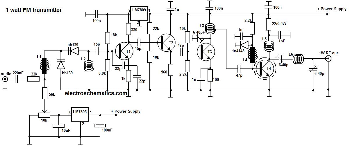
This is probably t he simplest radio transmitter that you will find anywhere. It has a total of five parts and can be constructed into a very small space. It is great for science fair projects or other science related projects where short range transmission is useful. It runs on 1. 5 to 3 Volts, with small. The following diagram is the FM transmitter circuit with FM transmision up to 4W. Voltage supply for this circuit is 12-16V with current consumption of 100-400mA. This circuit works with frequency of emission range of 88-108MHz. Components List: R1, R2 = 10K Ohm (1/4 W) R3 = 47 Ohm (1/4 W) C1, C2 = 1nF. This is a low cost and easy build low powered FM transmitter. The range of the FM transmitter claimed about 300 feets when running at 9V supply. And the range claimed to be increased become about 400 feet when running it at 12V supply. Take a note that this transmitter should not be used as. 🔗 External reference
Related Circuits
This low-power video transmitter is suitable for remote control applications, surveillance, or amateur radio. It employs seven transistors within a crystal oscillator multiplier RF power amplifier chain, along with a high-level video modulator. A supply voltage ranging from 9...
This portable FM transmitter features a limiter, a microphone amplifier, and PLL digital tuning, all integrated onto a single circuit board. The RF power output can be switched between 1 W (high) and 0.2 W (low). The schematic is...
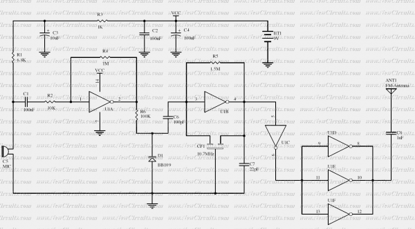
The RF oscillator using the inverter N2 and 10.7MHz ceramic filter is driving the parallel combination of N4 to N6 through N3. Since these inverters are in parallel, the output impedance will be low so that it can directly...
Most sound cards in computers lack stereo input for microphones, but they do have stereo inputs for high-level signals (Line). This circuit utilizes the Line input of the sound card to connect two mono microphones to the sound card's...
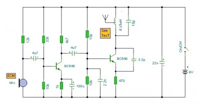
This is a mini FM transmitter circuit that utilizes two transistors. The audio sensitivity is notably high when paired with an ECM type microphone. The transmitter operates using a Hartley oscillator configuration. Typically, the capacitor in the tank circuit...
An oscillator can be constructed using an LC (inductor-capacitor) tank circuit. By varying the capacitance of the capacitor in the LC tank circuit, the frequency of the oscillator can be adjusted. An LC tank circuit serves as a fundamental building...