
AM DSB TRANSMITTER FOR HAMS

The AM transmitter circuit operates by generating an amplitude-modulated signal that consists of a carrier wave and two sidebands. The carrier frequency is the central frequency around which the sidebands are generated. The two sidebands, known as the upper sideband (USB) and lower sideband (LSB), are positioned symmetrically around the carrier frequency and carry the same information as the modulating signal.
In the design of the AM transmitter, various stages are involved, including the oscillator, modulator, and power amplifier. The oscillator generates a stable carrier frequency, which is typically achieved using a crystal oscillator or a phase-locked loop (PLL). The modulator combines the carrier wave with the audio or information signal, using a method such as linear modulation or switching modulation.
The power amplifier stage is crucial as it boosts the modulated signal to a level suitable for transmission. This stage must be designed to handle the required output power while maintaining linearity to prevent distortion of the modulated signal.
It is important to note that in a 100% modulated AM signal, a significant portion of the power (approximately two-thirds) is dissipated in the carrier, which does not carry any information. Consequently, only one-sixth of the total power is allocated to each of the sidebands, which actually convey the information being transmitted. This characteristic highlights the inefficiency associated with traditional AM transmission, prompting the exploration of alternative modulation techniques that optimize power usage and signal quality.
Furthermore, the design considerations for an AM transmitter include frequency stability, linearity, and efficiency. Adequate filtering must be implemented to suppress unwanted harmonics and spurious emissions, ensuring compliance with regulatory standards. Overall, the AM transmitter circuit is a fundamental component in the field of analog communication, enabling the transmission of audio and data over radio frequencies.The circuit of AM transmitter is designed to transmit (amplitude modulated) DSB (double side band) signals. A modulated AM signal consists of a carrier and two symetrically spaced side bands. The two side bands have the same amplitude and carry the same information. In fact, the carrier itself coveys or carries no information. In a 100% modulated AM signal 2/3 rd of the power is wasted in the carrier and only 1/6th of the power is contained in each side band.
🔗 External reference
Related Circuits

In 1896, Marconi successfully transmitted electromagnetic waves over a distance of approximately 3 kilometers. Shortly thereafter, he established radio communication across water between Lavernock Point in South Wales and Flat Holm Island. The transmitter utilized a spark inductor connected...
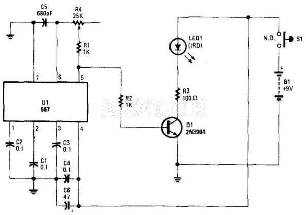
Using an NE567 as a tone oscillator, this circuit produces an infrared (IR) signal from the LED, which is modulated with a square wave. LED1 is an IR-emitting LED. The modulation enhances performance under high ambient light conditions. The circuit...

This transmitter emits an FM signal within the 88 to 108 MHz frequency range, featuring a tone of 19 kHz. This tone can activate the FM MPX pilot carrier indicator, allowing interfacing with external devices. L4 is designed for...
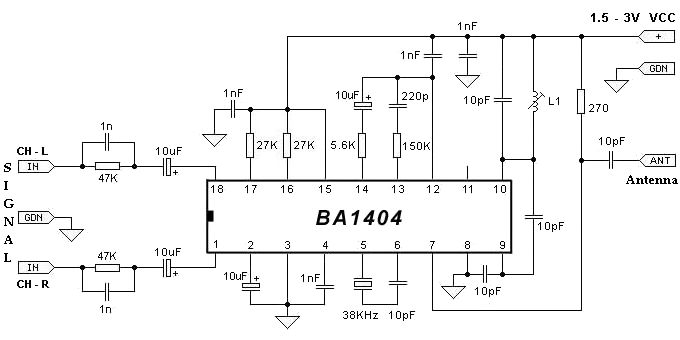
The BA1404 FM stereo modulator IC includes all the necessary components to design a simple, high-efficiency stereo transmitter circuit. It features a stereo modulator that generates composite stereo signals, an FM modulator for creating FM signals, and an RF...

This circuit diagram is part of an RF circuit. It features an FM transmitter circuit diagram using the BH1417 integrated circuit from RHOM, which incorporates multiple functionalities in a compact design. The IC includes pre-emphasis and a limiter to...
Small Radio Transmitter. This article contains information about building a small radio transmitter, which has a PCB measuring 1.75 x 2.5 inches (45 mm x 68 mm) and offers a range of approximately 30 yards. The small radio transmitter is...