
Small Radio Transmitter

The small radio transmitter is designed for basic communication applications and is suitable for hobbyists and educational purposes. The printed circuit board (PCB) dimensions of 1.75 x 2.5 inches (45 mm x 68 mm) allow for compact integration into various projects. The transmitter operates in the FM or AM band, depending on the design specifications, and is capable of broadcasting audio signals wirelessly within a range of approximately 30 yards.
Key components of the transmitter may include an oscillator circuit, which generates the carrier frequency, a modulator circuit to encode the audio signal onto the carrier wave, and an antenna for radiating the signal. The oscillator can be implemented using a simple transistor or an integrated circuit (IC) designed for RF applications. The modulator circuit typically employs a combination of resistors, capacitors, and transistors to ensure proper signal modulation.
Power supply considerations are crucial for the operation of the transmitter. A regulated DC power source, such as batteries or a wall adapter, should be used to ensure stable operation. Additionally, filtering capacitors may be included in the design to reduce noise and improve signal quality.
The antenna design plays a significant role in the effective transmission of signals. A simple wire antenna can be used, with its length adjusted to the frequency of operation to optimize performance. Proper placement of the transmitter and antenna can further enhance the effective range and clarity of the transmitted signal.
Safety precautions should be taken into account, particularly in regard to transmission power levels and frequency regulations to avoid interference with licensed radio communications. Overall, this small radio transmitter project offers a practical introduction to RF design and wireless communication principles.Small Radio Transmitter. This article contains information about building a small radio transmitter, which has a PCB 1.75 x 2.5 (45mm x 68 mm) and has a range of about 30 yards or. 🔗 External reference
Related Circuits

A typical low-cost FSK modulator, TA0038, is implemented by injecting the modulation voltage into the phase-locked loop (PLL) of the carrier synthesizer. This can be achieved in two ways: by summing the modulation voltage with the loop error voltage...

This application note outlines a cost-effective, high-performance UHF short-range Amplitude Shift Keying (ASK) receiver design utilizing the Microchip Technology rfRXD0420. The reference design is applicable for wireless remote command and control, remote keyless entry (RKE), and low-power telemetry applications....
Power supply: 12-14 V stab., 100 mA. RF power: 400 mW. Impedance: 50-75 ohm. Frequency range: 87.5-108 MHz. Modulation: wideband FM. Connect the 6 V / 0.1 A bulb to the output and use R1 to tune the right...
The following circuit illustrates a Radio Remote Control Circuit Diagram. This circuit is based on the UM91214B integrated circuit (IC) and features the use of DTMF (dual-tone multi-frequency) signaling. The Radio Remote Control Circuit utilizing the UM91214B IC is designed...
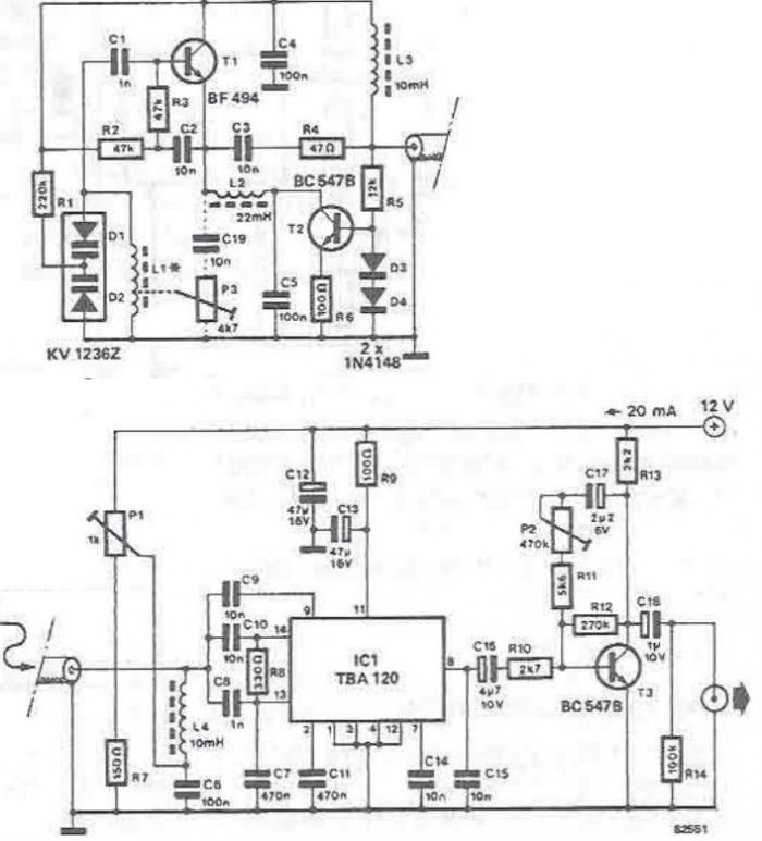
The tuning stage of this long-wave and medium-wave radio receiver also functions as an active antenna, which can be optimally positioned for the best reception. The circuit is completely independent from the receiver, which includes a demodulator that provides...
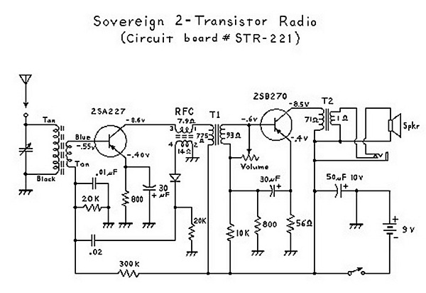
An analysis of certain radios reveals the impressive engineering by Japanese designers, particularly in creating a radio capable of driving a speaker with only two transistors. The first transistor (Q1) serves a dual function; it operates as an RF...