
AM radio circuit for electronics project

The radio circuit design incorporates several key components to achieve its functionality. The power supply, consisting of batteries, provides the necessary voltage and current for the circuit operation. A switch is integrated into the circuit to allow the user to turn the radio on and off, ensuring energy efficiency and user control.
The main audio output is delivered through a speaker, which replaces the traditional headphone output. To drive the speaker effectively, an additional amplifier circuit is employed. This amplifier is crucial for boosting the audio signal to a level that can adequately drive the speaker, ensuring clear and audible sound output. The amplifier circuit typically consists of operational amplifiers or dedicated audio amplifier ICs, configured to enhance the audio signal while minimizing distortion.
The decision to encase the components serves multiple purposes. It not only provides physical protection for the circuitry but also enhances the aesthetic appeal of the radio. The enclosure can be designed to facilitate easy access to the switch and speaker, enhancing usability. Furthermore, proper mounting of components within the case helps to reduce noise and interference, improving overall performance.
Overall, this radio project exemplifies a practical application of electronics principles, integrating power management, signal amplification, and user interface design into a cohesive and functional device.This functioning radio was built for my electronics module. The design that had been specified was modified to add batteries, a switch and a spea Read More This functioning radio was built for my electronics module. The design that had been specified was modified to add batteries, a switch and a speaker instead of headphones.
To do this we also required an additional amplifier circuit to power the speaker driver. Although not required, the group opted to mount the components in a case to make it a usable radio. Read Less 🔗 External reference
Related Circuits
A timing and counting circuit utilizing integrated circuit chips with seven-segment LED displays is employed to show the current lap time, previous lap time, and total number of laps completed on a 1/64th-scale slot car racetrack. A switch activated...
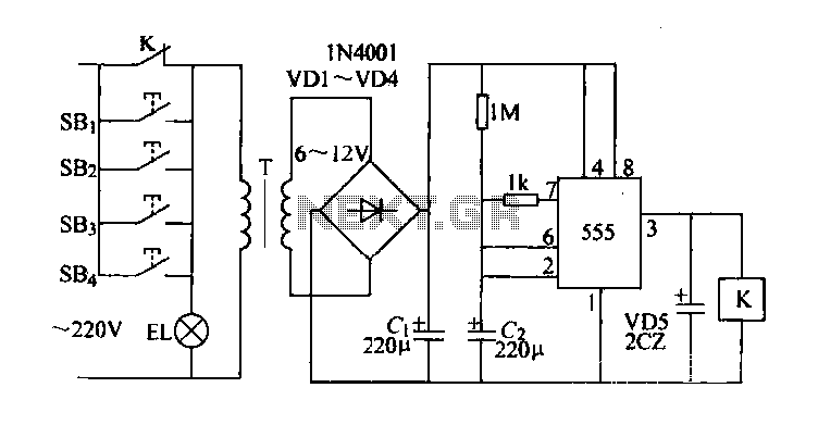
Control buttons SB1 to SB4 can be installed in various positions within a corridor. By pressing any one of these buttons, the EL horse lights will turn on. After releasing the button, the transformer and rectifier supply power to...
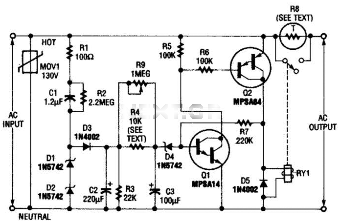
Q1 is an NPN Darlington transistor, and Q2 is a PNP Darlington transistor. MOV1 is a metal-oxide varistor, while R8 is a thermistor used for limiting inrush current. This circuit is designed to limit AC line current to a...
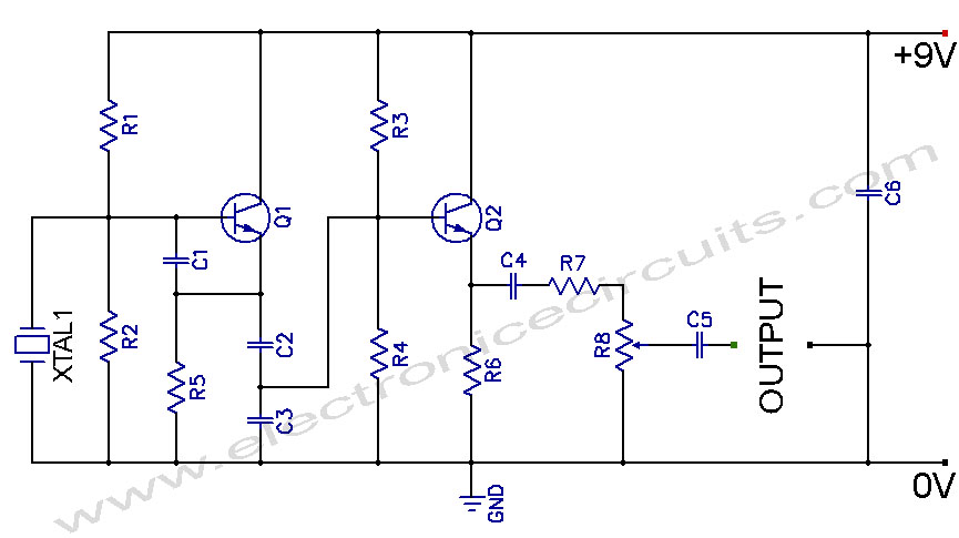
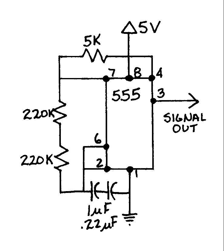
Crystal Controlled Oscillator Circuit. This general-purpose signal source is highly effective in signal-tracing applications. The output level is adjustable. The crystal-controlled oscillator circuit is designed to provide a stable and precise frequency output, which is essential for various electronic applications,...
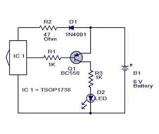
The cause may be dry solder joints, defective LEDs, or a flat battery (possibly due to a stuck key). The human eye cannot perceive infrared light, while a standard phototransistor such as the BP103 operates effectively in the infrared...
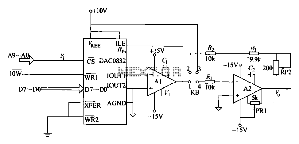
The DAC0832 is a digital-to-analog converter (DAC) chip designed for integration with computer bus systems. It features an 8-bit resolution and operates with a single power supply ranging from 5 to 15 volts. The device is compatible with TTL...