
remote circuit

The described circuit utilizes a combination of infrared sensing and sound output to create a responsive system that reacts to remote control signals. The BP103 phototransistor is pivotal in detecting infrared light emitted by the remote control, allowing it to trigger the BC558 transistor. This transistor acts as a switch for LED D1 and the buzzer, providing a visual and auditory response to the user’s commands.
The sensitivity of the system can be adjusted through a preset resistor, which modifies the threshold at which the phototransistor will activate the BC558. The interaction between the LED and the buzzer is synchronized with the frequency of the incoming signals, creating a dynamic feedback loop that varies based on user input. This feature enhances user experience by providing immediate feedback that correlates with the actions taken on the remote control.
The circuit requires a stable power supply, and the use of capacitors C1 and C2 is crucial in ensuring smooth operation. C1 filters the DC voltage to prevent fluctuations that could lead to erratic behavior, while C2 mitigates any transient spikes that could damage sensitive components.
The design of the sensor as a plastic-molded component allows for effective integration into a metal enclosure, which not only protects the circuit but also aids in aesthetic presentation. Grounding the metal case is a critical design consideration, as it helps to shield the circuit from electromagnetic interference (EMI) that may arise from nearby electronic devices, ensuring reliable operation.
Overall, this circuit exemplifies a well-thought-out design that incorporates various electronic principles to achieve a functional and user-friendly device. The layout and components are selected to optimize performance while maintaining a compact form factor, making it suitable for various applications where remote control functionality is desired.The cause may be dry solder joints, defective LEDs etc. , but also a flat battery (perhaps due to stuck key). The human eye is unable to perceive infra-red light. By contrast, an ordinary photo transistor like the BP103 has no problems working in the infrared spectrum, so in the circuit here it simply biases the BC558 which, in turn, makes LED D1 f lash in sympathy with the telegram from the remote control. The preset in the circuit determines the sensitivity. At the same time, the buzzer beeps at the same rate as the incoming signals from the remote control transmitter. The pressing of different buttons on the remote control will result in different pulse rates which would change the rate at which the LED blinks or the buzzer beeps.
When no signal is sensed by the sensor module, output pin 2 of the sensor goes high and, as a result, transistor T1 switches off and hence LED1 and buzzer BZ1 go off. This circuit requires 5V regulated power supply which can be obtained from 9V eliminator and connected to the circuit through a jack.
Capacitor C1 smoothes DC input while capacitor C2 suppresses any sudden spikes appearing in the input supply. Here, a plastic moulded sensor has been used so that it can easily stick out from a cut in the metal box in which it is housed.
It requires less space. Proper grounding of the metal case will ensure that the electromagnetic emissions which are produced by tube-lights and electronic ballasts etc (which lie within the bandwidth of receiver circuit) are effectively grounded and do not interfere with the functioning of the circuit. The proposed layout of the box containing the circuit is shown in the figure. The 9-volt DC supply from the eliminator can be fed into the jack using a banana-type plug. 🔗 External reference
Related Circuits

The simple pressure sensor alarm is constructed using a few inexpensive and readily available components. The operation of this circuit is straightforward and self-explanatory. When powered by a 9V compact battery, the active piezo sounder at the output of...

A simple 16-volt switching power supply circuit can be constructed using the provided diagram, which is based on the MAX668 constant-frequency, pulse-width modulating (PWM), current-mode DC-DC controller. This integrated circuit is designed for a wide range of DC-DC conversion...

One electronic ballast circuit is depicted in Figure 2-11. This circuit utilizes a specialized fluorescent lamp starter thyristor, SCR Y1112, which is superior to ordinary thyristors due to its ability to maintain a higher current value and dU/dt values....
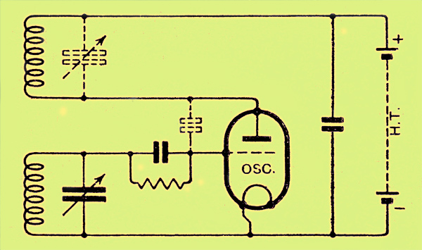
The congestion of the ether is increasing, prompting ongoing efforts to extend communication channels to higher frequencies. Wavelengths as short as 12 meters are now common, but operating below this presents significant challenges. At approximately one meter, the oscillation...

This circuit will activate a relay when light falls to a preset level. Light level can be adjusted with VR1 and the relay contacts may be used to operate an external light or buzzer. More: The light sensor used...

A simple thermostat circuit can be utilized to control a relay, which in turn supplies power to a small space heater via the relay contacts. It is essential that the relay contacts are rated above the current requirements for...