
Crystal Controlled Oscillator Circuit

The crystal-controlled oscillator circuit is designed to provide a stable and precise frequency output, which is essential for various electronic applications, particularly in signal tracing and testing. The core component of this circuit is a quartz crystal, which serves as a frequency-determining element. When the crystal is excited by an alternating current, it vibrates at its fundamental frequency, producing a consistent waveform.
The oscillator typically includes an amplifier, which is used to boost the signal generated by the crystal. This amplifier can be configured in various ways, such as a Colpitts or Clapp oscillator configuration, depending on the desired frequency range and output characteristics. The output level can be adjusted using a variable resistor or potentiometer, allowing for flexibility in signal strength to suit different applications.
Power supply considerations are also crucial for the performance of the oscillator. A stable DC power source is required to ensure the oscillator operates efficiently and consistently. The circuit may include bypass capacitors to filter out any noise, ensuring a clean output signal.
In addition to signal tracing, crystal-controlled oscillators are widely used in communication systems, frequency synthesizers, and clock generation circuits. Their high stability and accuracy make them suitable for applications requiring precise timing and frequency control. Overall, the crystal-controlled oscillator circuit is a fundamental building block in modern electronics, providing reliable signal generation for a variety of uses.Crystal Controlled Oscillator Circuit This general purpose signal source serves very well in signal-tracing applications. The output level is.. 🔗 External reference
Related Circuits
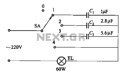
A dimming circuit capacitor circuit is illustrated in Figure 2-63. When the switch SA is moved from position "1" to "3," the capacitance increases in ascending order, resulting in the light bulb brightness also increasing correspondingly. When SA is...
The following diagram is for the main circuit of the motor driver. A testing version is shown near the end of this page. It is laid out differently and shows the SN7474 in logic block form and LEDs are...
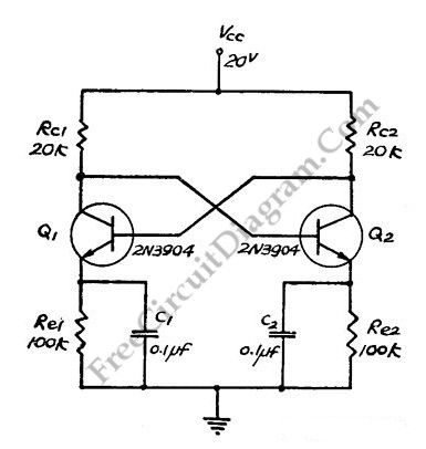
This flip-flop circuit functions as a free-running astable multivibrator, where the bases and collectors of both emitter-biased transistors are directly coupled. The switching action is facilitated by a capacitor in each emitter circuit, resulting in the generation of triangle...

The I2C PIC Interfacing Tutorial circuit is relatively straightforward; however, it requires careful verification to ensure that all connections are correct before initial operation. The primary components utilized in this circuit include the PIC18F452 microcontroller, the 24LC02B EEPROM, and...
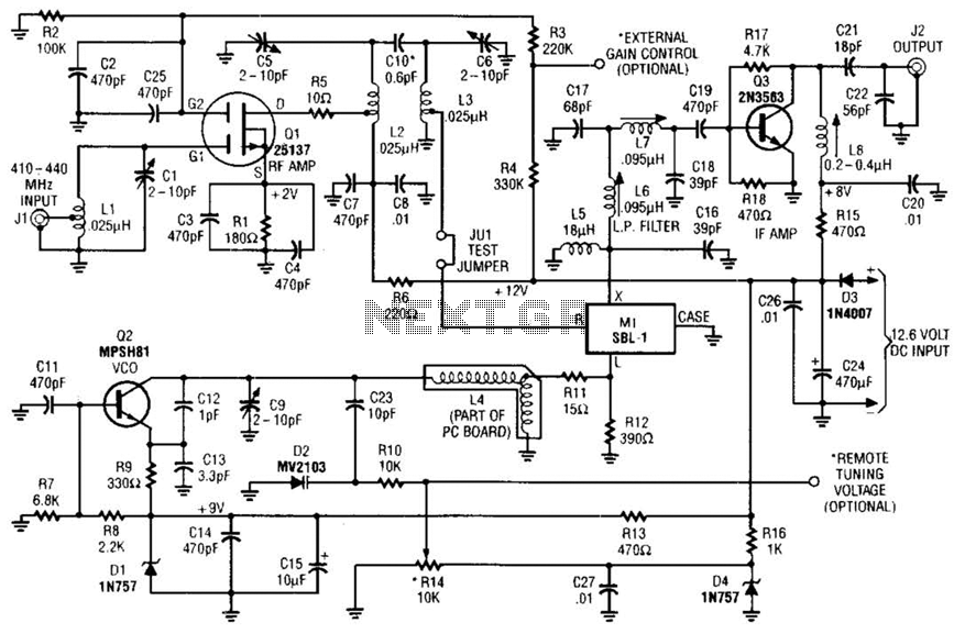
This RF converter converts amateur TV signals in the 420 to 450 MHz region to VHF channel 3 or 4, allowing reception of those signals on a standard TV receiver. RF amplifier Q1 feeds mixer M1, and Q3 acts...
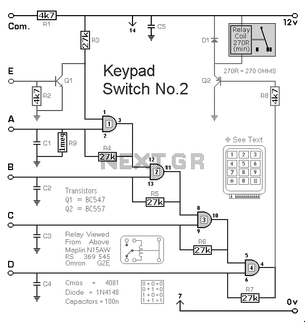
The Keypad Controlled Switch No2 Circuit operates with a 12-volt supply but is compatible with voltages ranging from 5 to 15 volts. The only requirement is to select a relay that matches the desired supply voltage. The Keypad Controlled Switch...