
AM radio intermediate frequency amplification and detection circuit

The AM radio circuit described encompasses essential components for the amplification and detection of intermediate frequency (IF) signals. The mixer serves as the initial stage, where the incoming RF signal is combined with a local oscillator signal to produce an IF signal. This IF signal is routed to the base of the transistor VT4, which is configured to amplify the signal. The collector load of VT4 connects to the primary winding of transformer T2, which is designed to resonate at 465 kHz, ensuring optimal signal transfer and amplification.
Transformer T2 plays a crucial role in filtering and isolating the desired IF frequency from unwanted signals. The inclusion of a 200 pF capacitor in parallel with the primary winding enhances the resonance, allowing for efficient signal processing. The secondary winding of T2 is connected to the base of the transistor VT5, which further amplifies the IF signal. This amplification stage is critical for maintaining signal integrity before it is sent to the detection circuit.
The output from VT5 is directed to intermediate frequency transformer T3, which serves as a coupling stage to the detection circuit. The detection circuit employs diodes VD4, which are responsible for demodulating the audio signal from the IF carrier. This process effectively removes the modulation, allowing the original audio signal to be extracted and forwarded to the audio power amplifier for further amplification and output.
Additionally, an automatic gain control (AGC) mechanism is implemented through a 12 kΩ resistor, which generates a control voltage applied to the base of VT4. This AGC signal helps maintain consistent output levels by adjusting the gain of the amplifier based on the input signal strength, thereby improving the overall performance and reliability of the AM radio circuit.AM radio shows of the IF amplifier and detector circuit. Mixer from the mixer IF output signal level of the intermediate frequency transformer after the device Ti, is applied t o the base of the intermediate frequency transistor VT4, VT4 collector load is intermediate frequency transformer primary winding T2, the primary winding 200 P parallel capacitor resonant circuit, resonant at 465 kHz, T2 secondary IF amplifier tube connected to the base of the pole VT5 by VT5 amplified IF signal, and then the intermediate frequency transformer T3 to the detection circuit, detector diodes VD4 modulated audio signal on an intermediate frequency carrier remove, transfer audio power amplifier, while forming via a resistor 12kn AGC signal is applied to the base bias on VT4.
Related Circuits
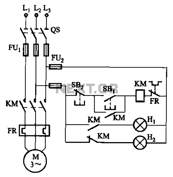
The circuit illustrated in FIG. 3 + 20 features SBi as the start button, SB2 as the stop button, Hi for run lights, and Hz for down lights. The subsequent circuit description aims to prevent tediousness by omitting the...
Servo motors are utilized in various applications, including robotics, puppetry, photography, and more. These compact motors can adjust their output shaft to a specified position on command and maintain that position. Most servos offer a range of motion of...
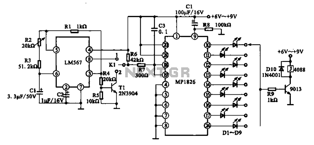
A precision circuit utilizing the LM567 timer, specifically the MPI826, where the LM567 functions as a dual-band oscillator. The MP1826 serves as a divider in the circuit, allowing the output signal from the LM567 to achieve extended timing. The...
The purpose of this circuit is to power a lamp or other appliance for a specified duration (30 minutes in this case) and then automatically turn it off. This feature is particularly useful for reading in bed at night,...
A highly accurate digital thermometer utilizing an LM35 probe with a resolution of 0.1 degrees Celsius. The circuit includes two adjustable components. The first, R5, is used to calibrate the display to zero. To perform this calibration, the end...
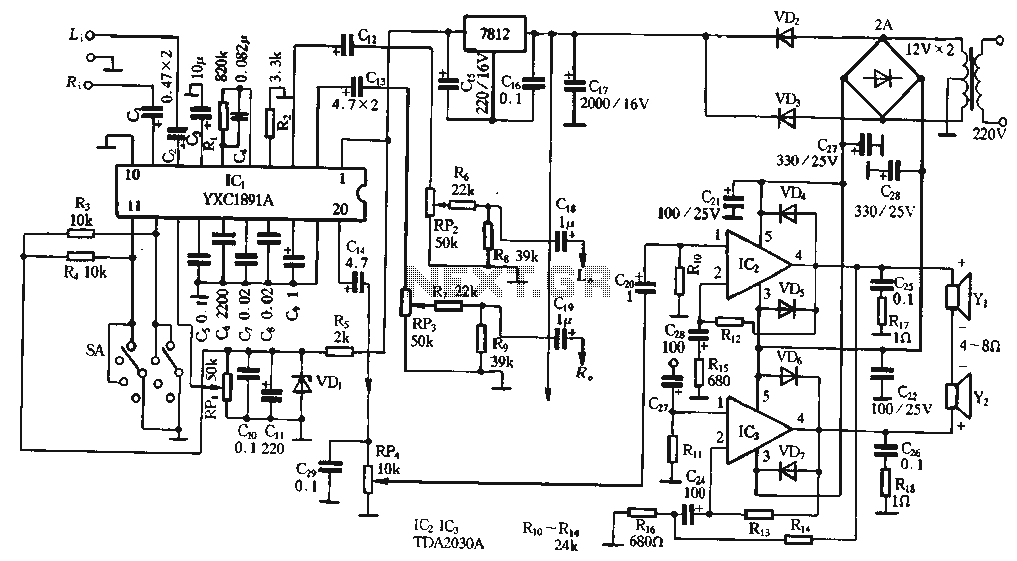
The ptPC1891A application circuit features a working state switch (SA) with a total of four options. It primarily utilizes ICs 11 and 12 to set different logical levels, as referenced in Table 5-12. The high level is denoted as...