
servo circuit

This circuit utilizes a 555 timer in astable mode to generate a pulse-width modulation (PWM) signal that controls the servo motor's position. The 555 timer is configured to produce a square wave output, which can be adjusted by varying the resistance of the potentiometer. The duty cycle of the PWM signal determines the angle of the servo motor's shaft, allowing for precise control over its position.
The circuit typically consists of the following components: a 555 timer IC, resistors, a potentiometer, a capacitor, and the servo motor itself. The potentiometer serves as an adjustable input, allowing the user to set the desired position of the servo. The output from the 555 timer is fed into the control wire of the servo, which interprets the PWM signal to position its shaft accordingly.
In practice, when the potentiometer is turned, it alters the resistance in the circuit, which in turn changes the timing of the 555 timer's output. This results in a variation of the pulse width, thus controlling the angle of the servo motor. The capacitor in the circuit helps to stabilize the signal and filter out any noise, ensuring smooth operation.
This type of circuit is advantageous due to its simplicity and low component count, making it accessible for hobbyists and educators. It serves as an excellent introduction to the principles of PWM control and the operation of servo motors, showcasing their versatility in various applications. The original publication in Popular Electronics highlights its relevance and utility in electronics education and practical applications.Servo motors have many uses in everything from robotics to puppetry to photography and beyond. These little motors can position their output shaft to any position on command and hold that position. Most servos have a range of motion to about 210 degrees and thankfully are very easy to control with a simple circuit such as the one presented here.
U sing just a 555 timer and a few support components this circuit can control a servo through it`s full rotation based on the position of a pot. This circuit was originally published in the Think Tank column of the October 1995 issue of Popular Electronics.
🔗 External reference
Related Circuits
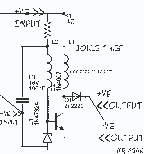
This circuit diagram is provided for those interested. It is a small circuit that takes an input of 1.5 volts and outputs 120 volts. The circuit in question is a voltage step-up converter, commonly referred to as a boost converter....
Implementing peak-detector circuits is straightforward with the CA3130, as illustrated in the schematic diagram of this circuit. The figure below presents the schematic diagram. The CA3130 is a high-performance operational amplifier that is well-suited for peak detection applications due to...
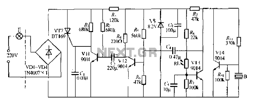
A modified piezoelectric ceramic acoustic-electric transducer is utilized to create a sound and light control system for a stairway walkway with a delay lighting switch. The circuit structure is relatively simple, consisting of diodes VD1 to VD4 and a...
The following circuit illustrates an Automatic Room Power Control Circuit Diagram. This circuit is based on the NE555 integrated circuit (IC). Features include the use of two Light Dependent Resistors (LDRs). The Automatic Room Power Control Circuit utilizes an NE555...
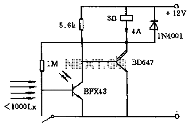
In the circuit's resting (dark) state, current flows through the electromagnet M. When light shines on the phototransistor, it turns on, causing the final stage transistor to enter the OFF state, which releases the solenoid. A 1M ohm feedback...
This circuit diagram illustrates the conversion of a speaker into a microphone. When sound waves impact the diaphragm of a speaker, fluctuations occur in the coil, generating an induced voltage. This induced voltage is typically substantial but low in...