
Light Dark switch activated relay circuits

The light-dark switch activated relay circuit operates by utilizing a photoresistor (R1) that detects ambient light levels. When the light intensity falls below a predetermined threshold, the resistance of the photoresistor increases, which alters the voltage at the base of the transistor (Q1). This transistor acts as a switch, controlling the relay's coil. The relay, when activated, can then power other devices, such as lights or alarms, depending on the application.
The R2 potentiometer allows for fine-tuning of the sensitivity of the circuit, enabling the user to set the exact light level at which the relay should activate. The diode (1N914 or 1N4001) is connected in parallel with the relay coil to protect the circuit from back EMF generated when the relay is de-energized. This protection is crucial for maintaining the longevity and reliability of the circuit components.
The circuit can be powered with a low voltage supply, typically between 5 to 6 volts, which is suitable for small electronic devices. The use of a 2N2222 transistor or its equivalents ensures that the circuit can handle the required current to activate the relay while providing sufficient gain to operate effectively. The overall simplicity of this design makes it an excellent choice for various applications, such as automatic lighting systems, garden lights, or security alarms, where activation based on light conditions is desired.This Light Dark switch activated relay circuits schematics are the simplest electronic circuits that can help you to activate other electronic device at the light or dark. This Light Dark switch activated relay circuits are very simple and require one electronic relay and other few common components that are not critical.
For electronic project you need to use a 5-6 volts electronic relay. The R2 potentiometer is used to adjust the trigger on level. The diode in the diagram shows to be 1N914. This is ok if you have a light-duty relay, also the 1N914 is a signal diode so actually does not qualify. If you don`t find the 1N914 you can substitute it with a 1N4001 diode (or better) instead. The 2N2222 (Q1) transistor can be substitute with :NTE123A, ECG123A, PN100, or other similar types. The R1 component is a photo resistor. 🔗 External reference
Related Circuits
The circuit consists of two stages. The first stage is a switch or cut-off device. It detects a voltage above 0.7V from the solar panel, and the resistance between its collector-emitter terminals reduces to a very small value. The...
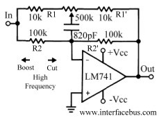
This discussion continues from the audio tone control topic, which introduced both passive and active tone controls. The follow-up topics may include a 2-Band Active Tone Control or a 3-Band Active Tone Control. An audio equalizer is utilized to...
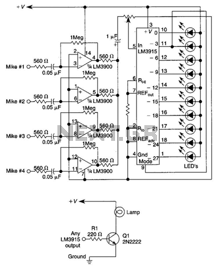
This circuit will produce an output when the sound exceeds a preset level. The LM3915 is a log-output bar graph driver. A transistor driver is used for higher current loads. To drive heavy-current loads with an LM3915 output, a...
This circuit is a two-wire light level detector, which does not separate the wires for power supply and output signal delivery. It operates using a current loop that performs both functions over a single pair of cables, requiring only...
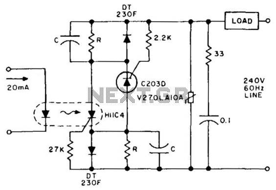
Latching is achieved by storing the gate trigger energy from the preceding half-cycle in capacitors. Power must be interrupted for more than one full cycle of the line to ensure turn-off. Resistor R and capacitor C are selected to...

The following circuit is a power amplifier circuit for an FM transmitter with an output power of 30 watts. The power amplifier circuit utilizes a power transistor of type 2SC1946A. The FM transmitter operates with a 13.8-volt DC power...