
AM Receiver

This regenerative receiver circuit is particularly advantageous for its simplicity and effectiveness in receiving medium wave signals. The use of three transistors allows for efficient amplification and demodulation of radio signals, making it suitable for hobbyists and educational purposes. The design's adaptability to higher frequencies with appropriate components enhances its versatility. The inclusion of feedback mechanisms facilitates fine-tuning of performance, allowing users to optimize sensitivity and selectivity according to their specific reception conditions. The construction of the tuning coil and the careful arrangement of components contribute to the overall functionality and reliability of the receiver. Furthermore, the potential for salvaging components from old devices promotes sustainability and cost-effectiveness in building this circuit.This is a compact three transistor, regenerative receiver with fixed feedback. It is similar in principle to the ZN414 radio IC which is now replaced by the MK484. The design is simple and sensitivity and selectivity of the receiver are good. All general purpose transistors should work in this circuit, I used three BC549 transistors in my prototyp e. The tuned circuit is designed for medium wave, but the circuit will work up to much higher frequencies if a different tuning coil and capacitor are used. I used a ferrite rod and tuning capacitor from an old radio which tuned from approximately 550 - 1600kHz.
Q1 and Q2 form a compound transistor pair featuring high gain and very high input impedance. This is necessary so as not to unduly load the tank circuit. Q1 operates in emitter follower, Q2 common emitter, self stabilizing bias is via the 120k resistor and the tuning coil. As Q2 operates in common emitter its base volatge will be a Vbe drop higher than ground or about 0. 71V in my test sample. The volatge at Q1 base will be this Vbe drop plus the voltage drop across the 1k resistor and Q1`s own Vbe drop, this amounted to 1.
34V from base to ground in my test circuit. For audio amplifiers, Q2 collector would be biased near half supply voltage, however the input signal levels at RF are tiny, typically 50uV appearing across the coil being amplified by Q2 and being about 5mV RF across the 2k2 load resistor. The 120k resistor provides regenerative feedback, between Q2 output and the tank circuit input and its value affects the overall performance of the whole circuit.
Too much feedback and the circuit will become unstable producing a "howling sound". Insufficient feedback and the receiver becomes "deaf". If the circuit oscillates, then R1`s value may be decreased; try 68k. If there is a lack of sensitivity, then try increasing R1 to around 150k. R1 could also be replaced by a fixed resistor say 33k and a preset resistor of 100k. This will give adjustment of sensitivity and selectivity of the receiver. Transistor Q3 has a dual purpose; it performs demodulation of the RF carrier whilst at the same time, amplifying the audio signal. Audio level varies on the strength of the received station but I had typically 10-40 mV, this is audio voltage, not RF signal level.
This will directly drive high impedance headphones or can be fed into a suitable amplifier. The tuning coil can be salvaged from an old AM receiver. However to make your own wind about 50 to 60 turns of 26 swg enamel coated copper wire over a 3/8 inch ferrite rod about 3 inches long. AM stations follow are directional so rotating the rod (or whole receiver) should allow nulling of some signals whilst boosting others.
If you are in an area of weak reception then an external antenna may be required. Wind about 4 or 5 turns (indicated as 4 or 5 T on the schmematic) of 26 swg wire onto the ferrite rod, close to the main winding and connect one end to a cold water tap or ground connection. Use several feet of flexible wire as an antenna. All connections should be short, a veroboard or tagstrip layout are suitable. The tuning capacitor has fixed and moving plates. The moving plates should be connected to the "cold" end of the tank circuit, this is the base of Q1, and the fixed plates to the "hot end" of the coil, the junction of R1 and C1.
If connections on the capacitor are reversed, then moving your hand near the capacitor will cause unwanted stability and oscillation 🔗 External reference
Related Circuits
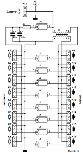
Receiver interference is a common issue among model builders. Preventive measures, such as ferrite beads fitted to servo cables, are frequently employed in larger models and electrically driven models to prevent the cables from acting as antennas and radiating...
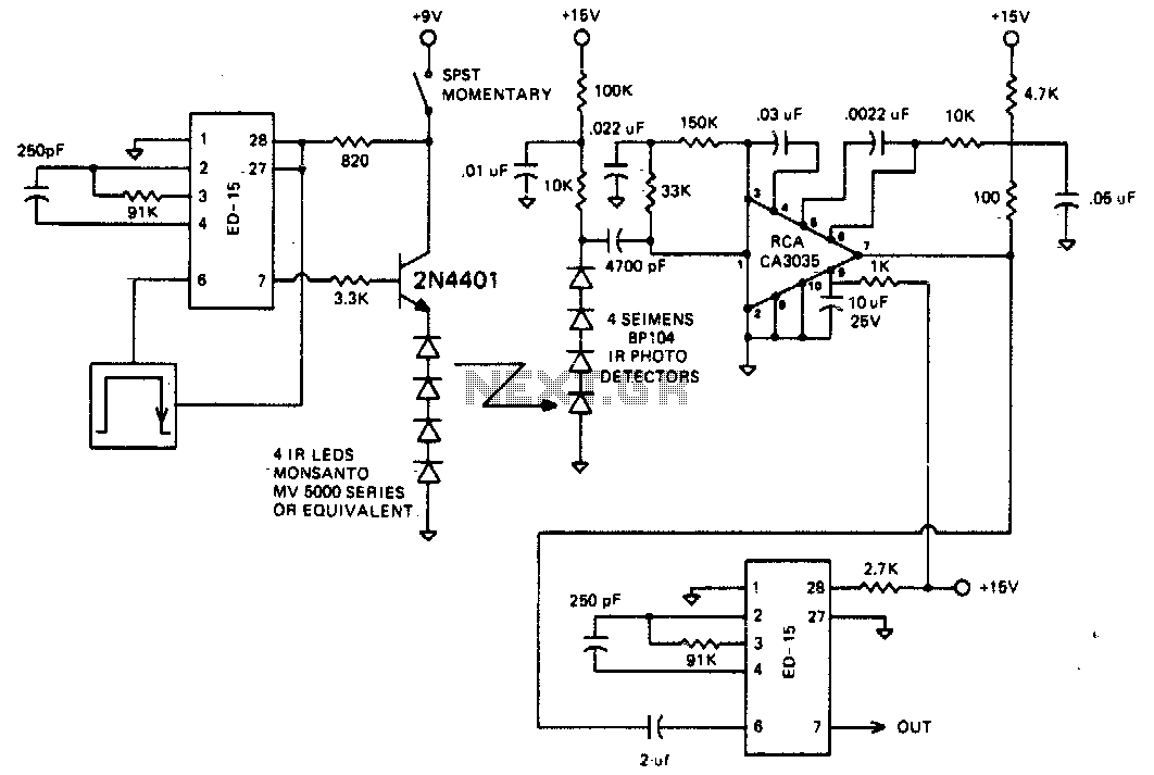
The circuit is designed to operate at 25 kHz. The data stream controls the 2N4401 transistor, turning it fully on or off based on the coded state. This action switches the series of infrared LEDs on and off. The...
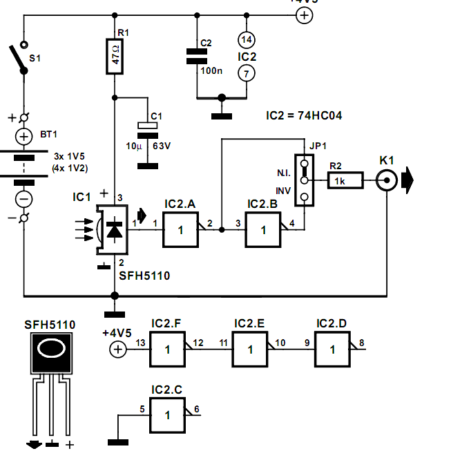
Many audio systems consist of separate units, and due to economic reasons, only the amplifier is equipped with a remote control receiver module. In audio system designs where components are split into separate units, it is common for only the...
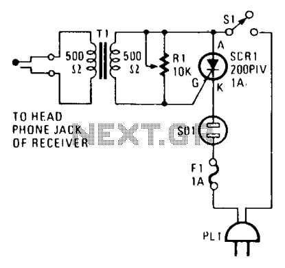
The alarm connects to the earphone jack on a receiver. When a signal, typically sent to the headphones, is detected and applied to the gate of SCR1, it conducts, activating the alarm connected to SOI. The signaling device can...
Many radio amateurs are interested in powering simple radio receivers using "free energy," which refers to energy obtained directly from the air via the receiver antenna. The circuits described can facilitate radio reception through a loudspeaker. However, questions remain...
Using the circuit of 40-metre band direct-conversion receiver described here, one can listen to amateur radio QSO signals in CW as well as in SSB mode in the 40-metre band. The circuit makes use of three n-channel FETs (BFW10)....