
IR remote control transmitter-receiver

The circuit operates at a frequency of 25 kHz, which is suitable for infrared communication applications. The 2N4401 transistor serves as a switching device that is driven by a data stream, which dictates its state. When the data stream indicates a high signal, the transistor is driven into saturation, allowing current to flow through the series of infrared LEDs. This results in the emission of infrared light, which can be detected by the receiver circuit. Conversely, when the data stream indicates a low signal, the transistor is turned off, ceasing the current flow and turning off the LEDs.
The receiver circuit is designed as a three-stage amplifier, which enhances the sensitivity and range of the system. The first stage typically includes a photodiode that converts the incoming infrared light into an electrical signal. This signal is then amplified in subsequent stages to ensure that even weak signals can be detected. The arrangement of photodiodes is crucial for maximizing coverage, allowing the system to effectively receive signals from various angles within a designated area.
The overall design ensures that the system can operate effectively within a range of approximately 10 meters, making it suitable for applications such as remote controls, wireless data transmission, and various infrared communication tasks. The choice of components, including the 2N4401 transistor and the configuration of the amplifier stages, contributes to the reliability and performance of the circuit in its intended applications.The circuit is designed to operate at 25 kHz. The data stream turns the 2N4401 hard on or off depending upon the coded state. This in turn switches the series infrared LEDs on and off. The receiver circuit consists of a three stage amplifier with photo diodes arrayed for maximum coverage of the reception area The range of this set-up should be about 10 meters.
Related Circuits
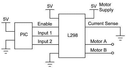
This article demonstrates how to control a DC motor using an H-bridge driver chip with PWM output from a PIC microcontroller for speed control. While a PIC microcontroller is utilized, other controllers such as AVRs, Basic Stamps, and certain...
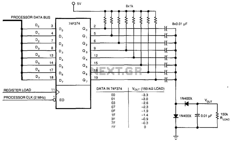
This circuit was used to produce a variable negative voltage for contrast control of an LCD display. A 74F374 generates a square wave that is AC coupled to a rectifier and load. By using the microprocessor clock and data...

As the only electronics engineer in the family and circle of friends, it is sometimes challenging to decline requests for assistance. Recently, a friendly elderly lady in a retirement home sought help regarding her lighting situation. In her room,...

The schematic for the board is illustrated below. The three primary components of the board include (1) the power input and voltage regulation, (2) the L297 input and outputs, and (3) the L298 stepper motor control circuit. The motor...
This add-on circuit enables remote switching on and off of battery-operated toy cars using a TV or video remote control handset that operates at 30 to 40 kHz. When powered by a 6V battery, the decade counter CD4017 (IC2),...
To sense and control the current in stepping motors and other similar devices, a linear integrated circuit such as the L6506 can be utilized. This chip set enables the formation of a constant current output. The L6506 is a versatile...