
Noise Suppression For R/C Receivers

The circuit design effectively addresses the challenge of receiver interference by employing a combination of ferrite beads, inductors, resistors, and capacitors strategically arranged on a compact circuit board. The use of ferrite beads on the servo leads serves to attenuate high-frequency noise, which is crucial for maintaining signal integrity, especially in applications where precise control is required. The isolation of power supply lines ensures that the noise generated by the servos does not compromise the performance of the receiver, which is essential for reliable operation in remote-controlled models.
In the schematic, the arrangement of components is critical for optimal performance. The ferrite-core inductor L10, rated at 2000 ohms at 30 MHz, is vital for suppressing high-frequency noise while maintaining the necessary current flow for the servos. Capacitors C1 and C2 work in conjunction with L10 to form a low-pass filter, effectively shunting high-frequency interference to ground. Resistor R1 may serve to dampen oscillations or further refine the filtering effect depending on the specific characteristics of the circuit.
The circuit board layout should prioritize short traces and minimal loop areas to reduce inductive coupling, which could introduce additional noise. Proper grounding techniques, including a solid ground plane, are essential to ensure that the filtering capabilities of the circuit are maximized. The inclusion of connectors K1 to K17 allows for easy integration with the receiver and servos, facilitating maintenance and upgrades to the system.
Overall, this design not only enhances the performance of the model by reducing interference but also contributes to a more organized and compact assembly, which is beneficial for both aesthetics and functionality in remote-controlled applications.Receiver interference is hardly an unknown problem among model builders. Preventive measures in the form of ferrite beads fitted to servo cables are often seen in relatively large models and/or electrically driven models, to prevent the cables from acting as antennas and radiating interference to the receiver. If miniature ferrite beads are used f or this purpose, the connector must be first be taken apart, after which the lead must be threaded through the bead (perhaps making several turns around the core) and then soldered back onto the connector. An interference source can also cause problems in the receiver via the power supply connection. The battery is normally connected directly to the receiver, with the servos in turn being powered from the receiver.
The servos can draw high currents when they operate, which means they can create a lot of noise on the supply line. This sort of interference can be kept under control by isolating the supply voltage for the receiver from the supply voltage for the servos.
All of these measures can easily be implemented loose` in the model, but it`s a lot nicer to fit everything onto a single small circuit board. That makes everything look a lot tidier, and it takes up less space. The schematic diagram is shown in Figure 1. Connectors K1 K8 are located at the left. They are the inputs for the servo signals, which are connected to the receiver by the servo leads. The outputs (K9 K16) are located on the right. That is where the servos are connected. Finally, the battery is connected to K17. Interference on the supply voltage line due to the motors and servos is suppressed by a filter formed by L10, R1, C1 and C2.
L10 is a ferrite-core coil with an impedance of 2000 ohms at 30 MHz. In combination with C1 and C2, it forms a substantial barrier to interference in the 35-MHz R/C band. Signals with frequencies close to the 10. 4-MHz intermediate frequency (which is used in many receivers) are also effectively blocked by this filter.
L9 filters out common-mode noise on the supply line for the servos, which effectively means that it prevents the supply lines to the servos from acting as antennas. Finally, high-frequency currents on the servo signals are filtered out by ferrite beads in order to limit the antenna effects of these connection lines.
🔗 External reference
Related Circuits
The tools used in this circuit are designed to create a noisy atmosphere. This circuit is relatively simple and is controlled by two 555 timer integrated circuits (ICs), assisted by other discrete components such as resistors and capacitors. The...
The notch filter can be integrated into nearly any receiver to attenuate a specific frequency by over 30 dB. This filter is particularly useful for diminishing heterodynes and whistles. A notch filter, also known as a band-stop filter, is designed...

Prior to the development of broadband communication receivers featuring synthesized oscillators, high-grade ham band receivers utilized crystal oscillators and a variable intermediate frequency (IF) to cover relatively narrow frequency segments of 500-600 kHz. The schematic illustrates a circuit designed...
It can safely charge a 7-cell RC2000 pack in about 14 minutes, and an RC2400 or CP2400SCR pack in about 17 minutes. As a NiCd cell is being charged, two things happen which affect its temperature. Due to resistive...
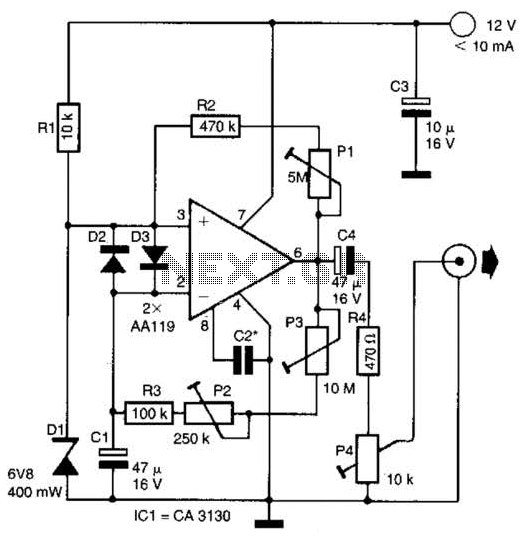
This circuit generates noise pulses suitable for test purposes. A Zener diode serves as the noise source. IC1 functions as a relaxation oscillator. P1 determines the noise bandwidth, while P2 and P3 control the noise amplification. The current consumption...
In broadband networking and high-speed computing applications, multiple high-current, low-voltage power supplies are required to power FPGAs, flash memory, DSPs, and microprocessors. One example specifies a maximum current of 60A to power the CPU at 1.5V and up to...