
AM RF Amp for Internal Antennas

This circuit is designed for compact electronic applications, particularly suitable for integration into small devices like Walkmans or other portable audio equipment. The use of a 1"x1" perf board suggests a focus on minimal space utilization, which is critical in modern electronics where real estate on PCBs is at a premium.
The circuit likely incorporates surface mount technology (SMT), which allows for a significant reduction in size compared to through-hole components. SMT components are soldered directly onto the surface of the PCB, enabling a denser layout and potentially improving performance due to shorter signal paths and reduced parasitic capacitance and inductance.
For optimal performance in audio applications, careful consideration must be given to the layout of the PCB. This includes minimizing ground loops, ensuring proper power supply decoupling, and maintaining signal integrity. The design may incorporate bypass capacitors close to power pins of integrated circuits to filter out noise and ensure stable operation.
The choice of components is also crucial. Low-profile capacitors and resistors should be selected to maintain the compact nature of the design. Additionally, the use of integrated circuits (ICs) that are specifically designed for audio processing can enhance the functionality of the circuit while keeping the size manageable.
When creating the PCB artwork, it is essential to follow best practices in PCB design, such as maintaining adequate trace widths for current carrying capacity, using vias judiciously to connect different layers, and ensuring that the layout adheres to the manufacturer's specifications for fabrication.
In summary, this circuit's design and assembly on a small PCB not only facilitate its integration into compact devices but also enhance performance through the use of modern SMT components and careful layout considerations.The author described assembling this circuit on a 1"*1" perf board, I actually laid out a small PC board with excellent results. In this era of surface mount components, I think a much smaller version can be laid out on a PC board, allowing this circuit to be put inside even the smallest radios, such as Walkmans.
If I do such a board, I will put the PC board artwork here. 🔗 External reference
Related Circuits
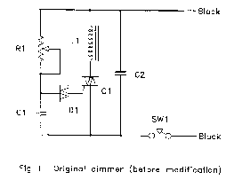
The circuit (before flameout) worked like this: device Q1 is a triac, which is a power-switching device. When triggered, it switches to a fully conducting state and stays that way until the current passing through it goes to zero....
The mechanical and electrical schematic in Figure 5 illustrates a simple circuit comprising several components. The first component is an electronic crossover section utilizing the NE5532 operational amplifier, which is known as the "Emperor of the op-amp." This section...

An emitter-coupled differential amplifier circuit is designed to suppress zero drift through circuit symmetry. The effectiveness of zero drift suppression improves with better symmetry; however, in practice, achieving complete symmetry is not feasible. Consequently, the basic differential amplifier circuit...

This is an economical 150 Watt amplifier circuit featuring two Darlington power transistors, TIP 142 and TIP 147. The circuit is capable of delivering up to 150 W RMS to a 4 Ohm speaker, providing substantial audio output. The...

R4 prevents the output voltage from drifting toward one of the supply rails of the operational amplifier. It is understood that R4 should have a high resistance, although the reason for this is unclear. The schematic appears to be...
The integrated circuit LM386 is a low-power audio frequency amplifier that requires a low-level power supply, typically batteries. It is available in an 8-pin mini-DIP package. The IC is designed to provide a voltage amplification of 20 without the...