
Current negative feedback electronic frequency power amplifier circuit

The schematic presented in Figure 5 encompasses a straightforward yet effective design for audio signal processing. The electronic crossover section is pivotal for dividing the audio signal into different frequency bands, ensuring that each band is directed to the appropriate amplifier stage. The NE5532 op-amp, renowned for its low noise and high performance, is configured to create a second-order filter, which is essential for achieving a smooth transition between frequency ranges. The cutoff frequency of 3.7 kHz is a crucial parameter that can be adjusted by modifying the values of the resistors and capacitors in the RC network, allowing for customization based on specific audio requirements.
In the power amplifier section, the TDA1514 and LM1875 are selected for their robustness in handling various frequency ranges. The TDA1514 is particularly effective for driving low frequencies, while the LM1875 excels in mid to high-frequency amplification. The innovative use of current negative feedback in this design stands out, as it enhances the amplifier's ability to respond dynamically to changes in load conditions. By sampling the current flowing through the speakers, the amplifier can make real-time adjustments, thus maintaining optimal performance and reducing distortion.
The feedback mechanism involving resistors R15 and R23 is integral to the circuit's operation. By incorporating the speaker into the feedback loop, the design effectively mitigates issues related to transient response, ensuring that the audio output remains clear and free from unwanted artifacts. This approach not only improves sound quality but also contributes to the overall reliability and efficiency of the amplifier system.
Overall, the schematic in Figure 5 exemplifies a well-thought-out design that leverages advanced electronic components and feedback techniques to deliver high-quality audio performance. The careful selection of components and the innovative feedback strategy are key factors in achieving superior sound reproduction.The mechanical and electrical schematic in Figure 5 112 in FIG. Chant is a schematic diagram of the channel can be seen from the figure, the entire circuit is very simple. It consists of the following components: (1) electronic crossover section 6 ICl as the "Emperor of the op amp," said the NE5532 mouth and around its RC element constitutes a typical second-order filter active input 6 after the signal points rather backward people behind the amplifier units amplify. According to the figure number, according to the crossover filter to 3. 7kHz, To change, simply calculated after changing the filter element can be RC. (2) power amplifier section of the heart IC3 TDA1514. LC4 the LM1875, which are as low, medium and high frequency amplification. It can be seen that the most part of the biggest difference amplifier circuit is that it increases the negative feedback amplifier circuit p general feedback voltage are all used in the form of negative feedback, and this machine is using the current negative feedback.
R15. R23 electricity flowing through the speakers stream sampling, back to the input of the amplifier, the amplifier is driven with a constant current load. Thus, the speaker has become a part of the negative feedback network, you can eliminate the effects of electro-acoustic impedance speaker system transient characteristics, the system transient distortion splash to a minimum, thereby improving the sound quality.
In addition, after using the current negative feedback, the output power amplifier
Related Circuits
555 timer circuits LM555 - Astable Oscillator Calculator, Capacitor Calculator, Basic Circuits for the LM555 Timer, Triggering and Timing Helpers for Monostable Timers, Controlling Circuits for LM555 Timers, Advanced Circuits for the LM555 Timer, LM556 Timers with Complementary or...
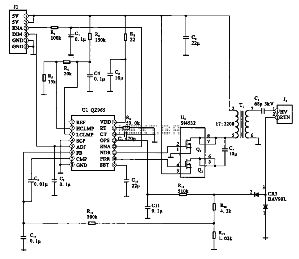
A typical liquid crystal display inverter circuit (OZ965) is primarily controlled by the OZ965 chip. It includes a driving field effect transistor (U2), a step-up transformer, the backlight socket, and associated circuitry. A 5V DC voltage is provided by...
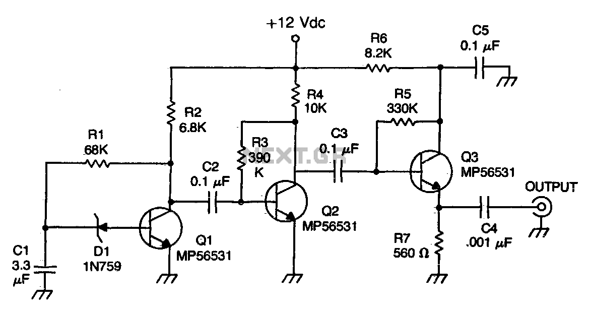
The Zener diode functions as an avalanche rectifier in reverse bias mode, connected to the input circuit of a wideband RF amplifier. The noise is amplified and subsequently applied to the cascade wideband amplifier, utilizing transistors Q2 and Q3. The...
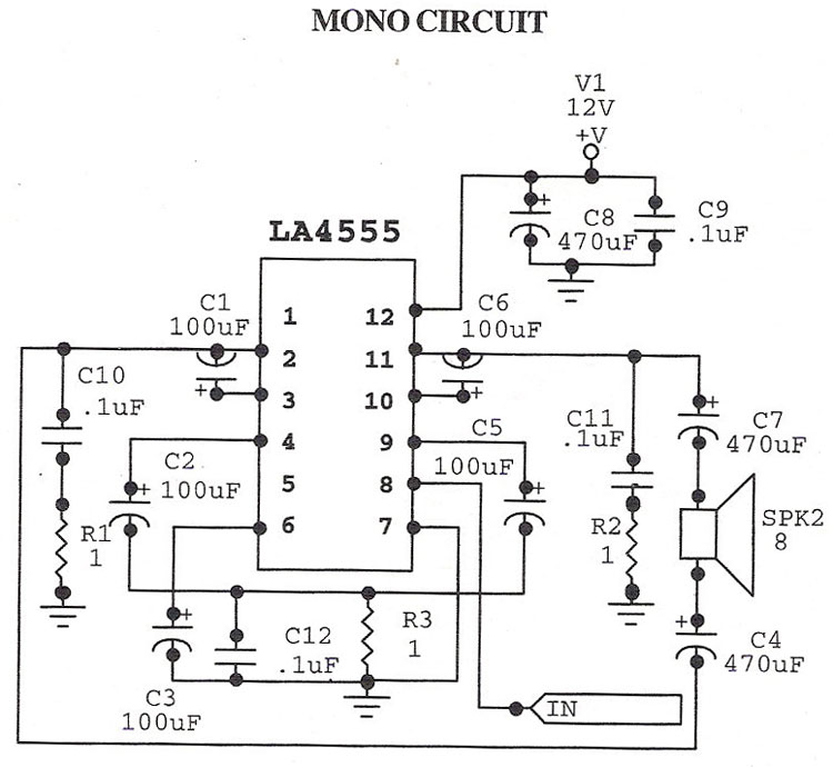
The LA4555 audio amplifier schematic includes both stereo and mono configurations. The LA4555 is primarily designed as a stereo amplifier, delivering 2.3 watts of power into 4-ohm speakers. The LA4555 audio amplifier is an integrated circuit designed for audio amplification...
This document outlines the theory behind a high-speed control scheme for an LED display screen circuit. The circuit utilizes the MCS51 series microcontroller to manage the LED display. A 62512 random access memory (RAM) is employed for data storage,...
The automatic sprinkler controller circuit consists of a +12 V power supply circuit, a light control circuit, and an irrigation control circuit, as illustrated in the accompanying figure. The +12 V power supply circuit includes a knife switch (Q),...