
Ammeter with six decade range II

The ammeter described operates within a current range of 100 picoamperes (pA) to 100 microamperes (µA), making it suitable for applications requiring precise low-current measurements. The absence of high-value resistors in the design not only reduces costs but also minimizes additional noise and power consumption, which is critical when measuring such low currents.
The accuracy of the ammeter at the upper limit of 100 µA is primarily constrained by the offset voltage between the two transistors, Q1 and Q2. This offset voltage can introduce errors in the current measurement, necessitating careful selection and matching of these components to ensure high accuracy. The influence of temperature and manufacturing variances on the offset voltage must also be considered during the design phase.
At the lower limit of 100 pA, the performance is affected by the inverting bias current of the LT1008 operational amplifier. This bias current can contribute to measurement errors, especially in low-current scenarios where even minute variations can significantly impact the reading. To mitigate this effect, the circuit design should include strategies such as using low-bias current operational amplifiers or employing techniques to minimize the impact of bias currents on the measurement.
In summary, the ammeter effectively measures a wide range of currents while maintaining cost efficiency by avoiding high-value resistors. However, it is crucial to address the limitations imposed by the offset voltage of the transistors and the bias current of the operational amplifier to achieve optimal accuracy across the specified current range.The Ammeter measures currents from 100 pA to 100 µ without the use of expensive high value resistors. Accuracy at 100 µ is limited by the offset voltage between Ql and Q2 and, at 100 pA, by the inverting bias current of the LT1008.
Related Circuits
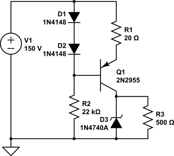
A simple low voltage/current power supply that can accept a wide range of input voltages, up to several hundred volts. The input range is specified as 20 to 160V DC, with an output requirement of 10V and a maximum...
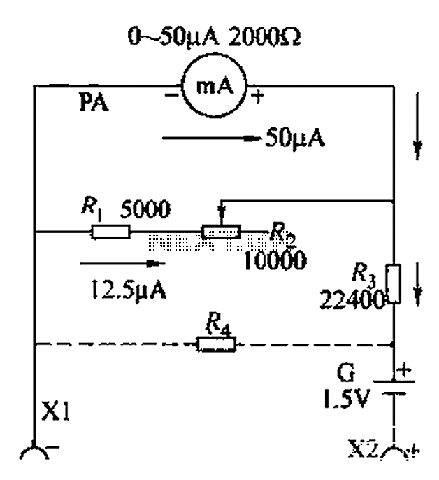
A commonly used high-sensitivity header utilizes a microammeter to create a resistance meter capable of measuring very low voltages. The design adheres to the principles of a milliameter resistance meter. The circuit diagram is illustrated in Figure 5-37, which...
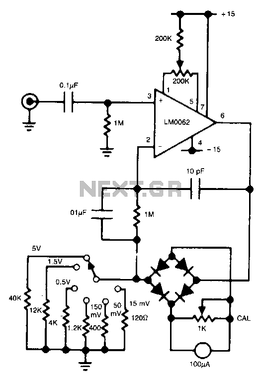
In this circuit, a diode bridge is utilized as a meter rectifier. The offset voltage is compensated for by the operational amplifier, as the bridge is part of the feedback network. The circuit employs a diode bridge rectifier, which consists...
This converter allows reception of six metre signals on a two metre receiver. It should therefore be useful for those with single or dual band sets that do not cover 50 MHz. More: To eliminate the need to obtain...
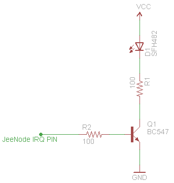
This schematic effectively doubles the range of an infrared (IR) LED, with the circuit now drawing 37mA of power. In contrast, the previous circuit, which did not utilize an NPN transistor, drew 20mA, which is the maximum current per...
A phase-locked loop (PLL) is a servo system, or a feedback loop that operates with frequencies and phases. PLLs are known to be quite useful in communication systems, where they can extract small signals from significant noise. This discussion...