
Ammo Box Sequencer
Operation: Before the "chase start" cue, the power and reset toggle switches should be flipped on (up) simultaneously. The speed and direction should be set to predetermined settings based on experimentation. Upon cue, the start toggle switch should be flipped on (up) and released. The A LED and circuit will illuminate, and the chase will proceed in the pattern determined by the pattern select toggles. Changing the pattern select toggles while the chase is running may yield unpredictable results but will not damage the circuit. Holding the start toggle for two timing pulses will light both the A and B circuits and initiate their chase. Assuming the pattern select is set to A-B-C-D, the resulting chase will be AB-BC-CD-DA. Holding the start toggle for three pulses will produce ABC-BCD-CDA-DAB, creating an effect where all lights are on with an "off" light chasing A-B-C-D. An additional component, the 74157 (4 pole double throw switch equivalent), can be integrated into the original sequencer circuit to allow for reversing the direction of the sequence. With an A-B-C-D sequence, flipping this switch will yield a D-C-B-A chase.This is the Sequencer circuit. Power to the Logic portion of the circuit is provided by a standard commercial "wall-wart" power adaptor supplying 6 VDC. The 555 timer IC provides the pulse train that drives the chase; the timing is adjustable with the 100K potentiometer.
The two 22K resistors and the 1uF capacitor were selected to run the 555 in a syncronous mode where it constantly emits pulses (at pin 3) as soon as and as long as power is supplied. The pulse train from the 555 is connected to the clock of the 75175 (Quad D Flip-Flop) IC. The 75175 is the heart of the chase logic. A pulse from the Start switch is fed into D1; at the next clock pulse Q1 is turned on. D2, D3, and D4 in turn are set, depending on the settings of switches S1, S2, and S3. The not-Q outputs of each flip-flop are used to drive the A, B, C, and D LEDs to let the operator see the chase independant of any AC-powered lamps.
The Q outputs drive the opto-isolators (MOC3010) into triggering the triacs that switch the AC power. I built this Sequencer using a standard military 50-cal ammo box for the case. The ammo box is water tight and weatherproof, and I used toggle switches with waterproof covers on the control panel so that this controller could be safely used outdoors.
One long side of the box held all the controls and indicators; the AC power cords and outlets were mounted on one end. The circuit is designed to use four independant, dimmable, power feeds - one for each circuit. If needed, the triacs and fuses for each circuit can be rated for up to 20 amps. The square symbols with two Vs on top represent terminal blocks with spade lugs; these allow the circuit board to be unplugged and removed from the ammo box.
The power to the wall-wart is via a fifth power cord, the hole for which is not on the template. While assembling the box I added a neon lamp for each circuit, wired in series with a current-limiting resistor. The resistor was connected to the same terminal block as the fuse, the other neon lamp wire connected to the AC neutral on the socket.
The neon lamp acts as a "fuse is good" indicator; the holes for the neon lamps are to the right of the fuses on the diagram. Operation: at any time prior to the "chase start" cue, flip the Power and Reset toggle switches on (up) simultaneously.
Set the Speed and Direction to previously determined (by experimentation) settings for this cue. On cue, flip the Start toggle switch on (up) and release. The A LED and circuit will light, and the chase will proceed in the pattern set by the Pattern Select toggles. (Changing the Pattern Select toggles while the chase is running will yield unpredictible results, but will not harm the circuit.
) If you hold the Start toggle on for two timing pulses, both the A and B circuits will light and chase. Assuming the Pattern Select is for A-B-C-D, the resulting chase will be AB-BC-CD-DA. Holding Start on for three pulses yields ABC-BCD-CDA-DAB-, which appears to be all lights on and an "off" light chasing A-B-C-D.
This 74157 (4 pole double throw switch equivalent) circuit is an add-on to the original Sequencer circuit. It adds a switch to the Sequencer that allows the direction of the sequence to be reversed. Assuming an A-B-C-D- sequence, flipping the switch yields a D-C-B-A- chase. 🔗 External reference
Related Circuits
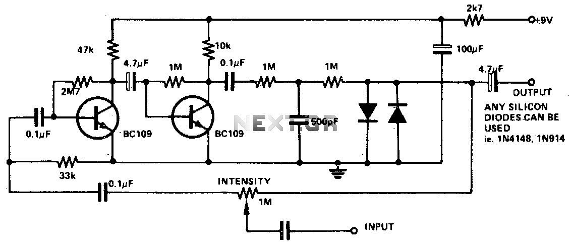
The input signal is amplified by the transistors. The distorted output is then clipped by the two diodes, and the high-frequency noise is filtered from the circuit via the 500 pF capacitor. The 1 M potentiometer adjusts the intensity...

This circuit was designed to obtain a valve-like distorted sound from an electric guitar or other musical instrument. For this purpose a very high gain, three-FET amplifier circuit, was used. The output square wave shows marked rounded corners, typical...
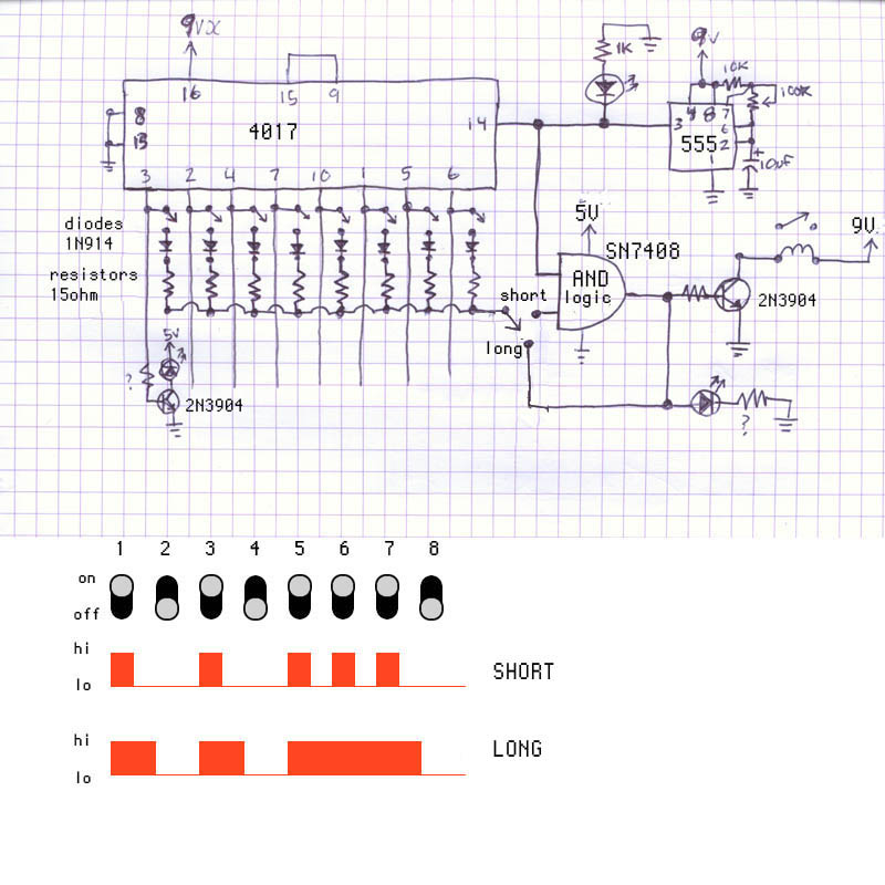
The interesting aspect of the 4017 is its capability to be cascaded with other 4017s to extend the sequence length, albeit requiring additional discrete components. The schematic in question was one of the few cascading designs available for the...
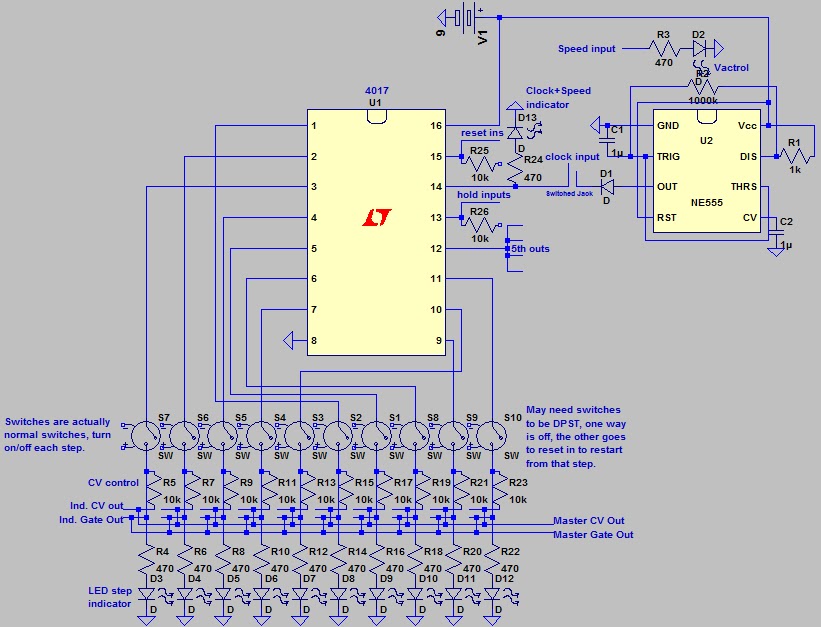
Below is the clock section. The knob controls the speed of the internal oscillator, which can be voltage-controlled via the Speed In input. Alternatively, a user-defined clock signal can be inserted via the Clock In. This feature is somewhat...
A 1999 S10 2.2L Fuse Box inquiry involves identifying the main power terminals located at the top left and right of the Fuse Box. The question pertains to which terminal serves as the full-time power terminal and which one...
This circuit creates a buzz coil using a standard automotive ignition coil. A 556 dual timer is employed to establish the frequency and duty cycle of the coil current. One timer functions as an oscillator to generate the 200...