
Amp Gain Block

The circuit employs a triode amplifier configuration where the second triode's plate is directly coupled to the first triode's cathode, facilitating a DC feedback loop. This design choice enhances stability at low frequencies compared to previous AC coupling designs, which suffered from instability issues. The 220 k ohm load resistor influences the distortion characteristics of the second triode, making it a critical component in maintaining audio fidelity.
In terms of feedback management, the circuit design requires careful selection of component values. The feedback resistor (Rf) plays a crucial role in determining the operating point of the second triode; thus, any alterations to this resistor necessitate recalibration of the cathode resistor to ensure minimal distortion.
The presence of a 1 dB peak in the frequency response below 10 Hz, observed during simulation, highlights the importance of balancing feedback types. The negative feedback to the first triode's cathode must be managed alongside the positive feedback to the grid to avoid adverse effects on gain. The adjustment of coupling capacitor sizes is a strategic approach to achieving desired frequency response characteristics, ensuring that any positive feedback is attenuated appropriately.
The amplifier's design philosophy prioritizes low distortion and stable operation, making it ideal for applications where high fidelity and precise gain control are paramount. This circuit can be effectively employed in audio amplification systems where performance consistency and low output impedance are required.You see that the feedback is DC coupled, not through a capacitor, from the plate of the second triode to the cathode of the first. An earlier design used AC coupled feedback. This version was unstable at low frequencies. Bode analysis showed that a 3 microfarad coupling capacitor would have been needed to make it stable.
The 220 k ohm resistor makes up most of the load for the second triode which is where most of the distortion occurs. I don`t recommend changing the value of Rf because it effects the operating point of the second triode. If this resistor is changed the cathode resistor in the second triode will have to be readjusted for minimum distortion.
Someone emailed me with the information that when this circuit was run on a spice simulator there was a 1 dB peak in the frequency response below 10 cycles. This really isn`t very important but it still might bother some people. It was caused by the fact that the feedback which goes to the cathode of the first triode and is negative also is fed in a small amount to the grid which is positive feedback.
I downloaded a spice simulator and checked it out and confirmed the peak. The trick is to adjust the relative sizes of the inter-stage coupling capacitor and the input coupling capacitor so the positive part of the feedback is rolled off before it can effect the gain. I also tested it with the volume control set at half resistance which is the maximum impedance condition.
The roll-off is now smooth at both ends. I trust everyone, perfectionists included, can now sleep. Am I a perfectionists Well, grudgingly, yes. You may be wondering why I have gone for such low distortion while on other pages of this section I didn`t indicate it was that important. This amplifier is NOT meant to be inside the global feedback loop. As such it needs to have an inherently low distortion level because nothing is going to improve it later.
This circuit may be used where ever a stage with low distortion, relatively low output impedance, and closely controlled gain is required. 🔗 External reference
Related Circuits
This FM RF amplifier utilizes two transistors from Philips: the BLV 10 and the BLW 87. The two RF transistors are configured in a chic C arrangement, providing an overall gain of 21 dB (100 times) with an efficiency...
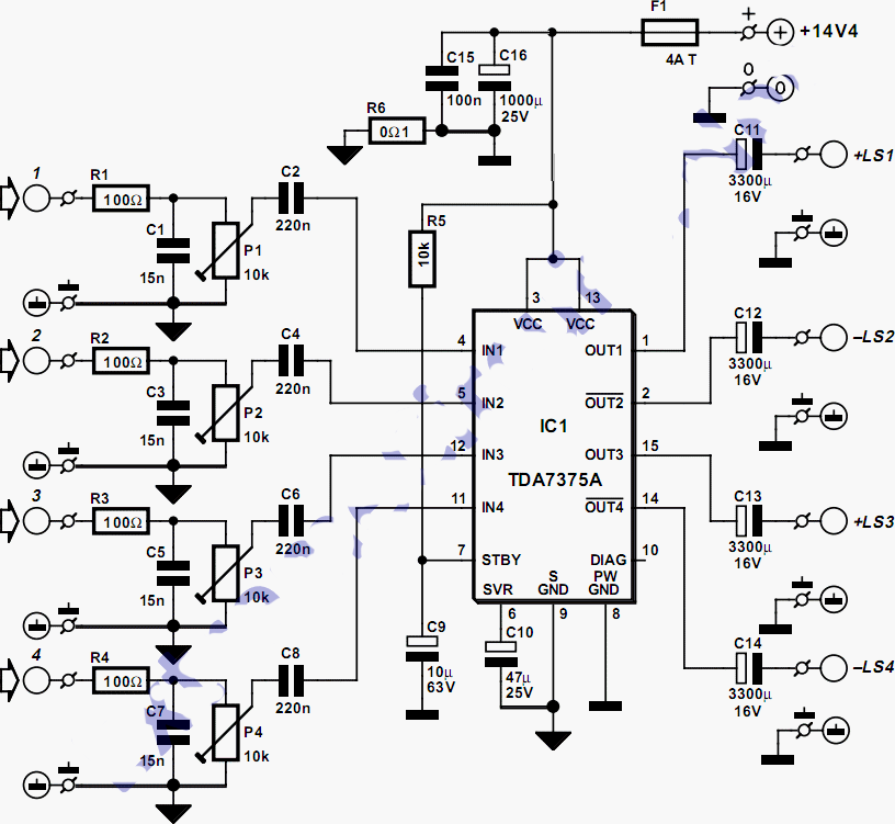
This quad amplifier is designed primarily for automotive use but can also be applied in various medium-power scenarios. The TDA7375A is suitable for situations requiring a reasonable amount of audio power with a relatively low supply voltage. It is...

A similar circuit can be utilized with an 8-ohm speaker; in this instance, it should be placed in the position of the emitter resistor. This circuit functions as a replacement for a carbon microphone. The described circuit is intended for...
This simple circuit generates narrow pulses at about 700-800Hz frequency. The pulses, containing harmonics up to the MHz region, can be injected into audio or radio-frequency stages of amplifiers, receivers and the like for testing purposes. A high-pitched tone...
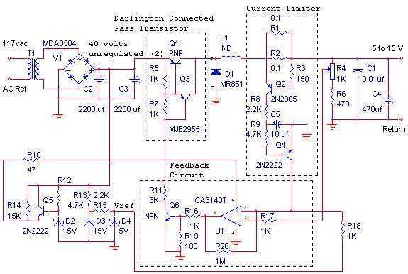
The switching power supply, shown in the schematic, provides 12 volts, at 10 amps, maximum, using a discrete transistor regulator with an op-amp functioning as a comparator in the feedback circuit. The supply was constructed in 1984 and is...
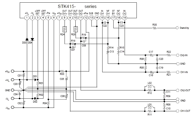
This electronic project stereo amp is based on the STK415-090-E class H audio power amplifier hybrid IC that features a built-in power supply switching circuit. This STK415-090-E class H audio power amplifier provides high efficiency audio power amplification by...