
12 Volt, 10 Amp Switching Power Supply

The described switching power supply operates at a nominal output of 12 volts and a maximum current output of 10 amps. It employs a discrete transistor regulator, which is a notable choice for its simplicity and effectiveness in converting input power to the desired output. The inclusion of an operational amplifier (op-amp) as a comparator in the feedback loop is critical for maintaining voltage regulation. This configuration allows the system to compare the output voltage to a reference voltage, adjusting the transistor's conduction to stabilize the output.
The design, dating back to 1984, utilizes a variable frequency approach rather than modern pulse width modulation (PWM) techniques. This can impact efficiency and thermal performance, as variable frequency operation may lead to less optimal switching characteristics compared to PWM methods prevalent in contemporary designs.
The schematic indicates that the front panel power-on indicator light is not depicted, which may be a consideration for user interface design. Furthermore, the absence of an adjustable current limiter suggests that the power supply is intended for applications where a fixed current limit is sufficient. The components R1, R2, R3, Q2, R8, R9, C5, and Q4 collectively establish the current limit at approximately 10 amps, ensuring protection against overcurrent conditions.
Overall, while the design reflects the technology of its time, it demonstrates fundamental principles of power supply design that remain relevant, such as feedback regulation and current limiting. The circuit's simplicity may also contribute to reliability, making it suitable for various applications where precision and stability are required.The switching power supply, shown in the schematic, provides 12 volts, at 10 amps, maximum, using a discrete transistor regulator with an op-amp functioning as a comparator in the feedback circuit. The supply was constructed in 1984 and is variable frequency, as opposed to the pulse width modulator (PWM) controllers used today.
With reference to the schematic, the front panel power-on light is not shown. There is no adjustable current limiter in this unit, although R1, R2, R3, Q2, R8, R9, C5 and Q4 set the current limit to approximately 10 amps. As you can see, the design is ver 🔗 External reference
Related Circuits
This amp uses the basic circuitry of the 60W power amp but modified for true Class-A operation. This amp has been built by several readers, and the reports I have received have been very positive. With simulations, everything appears...
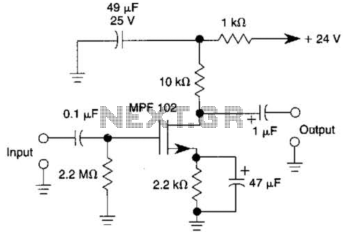
This JFET preamplifier has a gain of approximately 20 dB and a bandwidth exceeding 100 kHz. It is useful as a low-level audio amplifier for high-impedance sources. The described JFET (Junction Field Effect Transistor) preamplifier is designed to amplify low-level...
This is a circuit diagram of an audio amplifier circuit featuring a 10W power amplifier using the TDA2003 integrated circuit from SGS Thomson. The IC is capable of delivering 10W into a 4-ohm load at a supply voltage of...
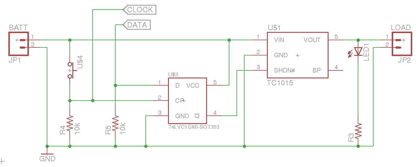
A soft power switch for a microcontroller is designed such that a momentary switch can activate the circuit, including the microcontroller. When the switch is pressed a second time, the microcontroller is capable of shutting itself down after executing...
A person visiting the website is interested in a DC voltage adjustable regulator that can output between 1.2V to 12V with a current capacity of 1-2A. Initially, the individual considers using the LM317 integrated circuit for this purpose. However,...
The power supply section is the important one. It should deliver constant output regulated power supply for successful working of the project. A 0-12V/500 mA transformer is used for this purpose. The primary of this transformer is connected in...