
Dynamic Mic Preamp

The described circuit is intended for applications where a carbon microphone is traditionally used. By substituting the emitter resistor with an 8-ohm speaker, the circuit allows for audio output instead of the original microphone function. This configuration can be advantageous in various audio processing applications, where the speaker can serve as an output device, converting electrical signals back into sound.
In this circuit, the 8-ohm speaker operates effectively due to its impedance matching with the output stage of the amplifier. The emitter resistor typically plays a crucial role in biasing and stabilizing the transistor's operation. By replacing it with a speaker, the circuit now allows for sound generation, which can be beneficial in scenarios such as voice transmission or sound feedback systems.
The circuit may consist of a transistor configured in a common emitter arrangement, where the input audio signal is applied to the base terminal. The transistor amplifies this signal, with the collector connected to the power supply and the emitter connected to the 8-ohm speaker. The output sound is produced as the amplified signal drives the speaker, converting the electrical energy back into audible sound waves.
When designing such a circuit, attention must be paid to the power ratings and frequency response of the speaker to ensure optimal performance. Additionally, appropriate coupling capacitors may be necessary to block DC components while allowing AC signals to pass through, preserving the integrity of the audio signal.
This configuration demonstrates a versatile approach to audio signal processing, providing an alternative to traditional microphone setups while maintaining functionality in sound reproduction applications.A similar circuit can be used with an 8 ohm speaker but in that case you would put it in place of the emitter resistor. This circuit works as a carbon microphone replacement. 🔗 External reference
Related Circuits
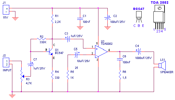
A small amplifier with nice characteristics: Tendency of catering: 15V. Force of expense: 4.2Wrms in the 4W. Minimal signal of entry: 94mVp-p with preamplifier, 0.65Vp-p without the preamplifier. More: Materially: R1=2.2kΩ R2=330kΩ R3=4.7kΩ logarithmic potentiometer R4=330Ω R5=1kΩ R6=1.5Ω C1,...
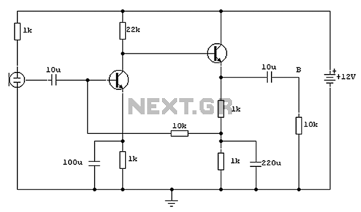
Both transistors utilized in the circuit are low-noise types. Initially, the BC650C, an ultra-low noise device, was employed. However, due to its scarcity, the BC109C serves as a suitable replacement. The circuit exhibits a high tolerance for various devices...
Preamps may in some cases use a simple regulator, with the supplies taken from the main amp power supply. This can be a problem if the main amp is of very high power, as the supply voltage will be...
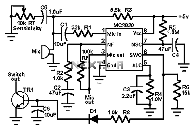
The circuit schematic utilizes the MC2830 voice circuit. Traditional voice circuits are unable to differentiate between speech and noise in the input signal. In noisy environments, such as those caused by switches, this limitation is significant. To address this...
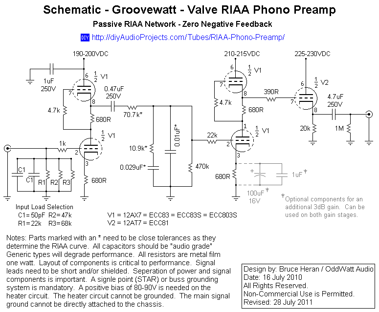
This project has been in development for over a year, initially postponed due to concerns about design complexity and the availability of high-quality phono preamps. The objective was to create a preamp that would deliver performance comparable to commercial...
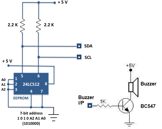
For beginners experiencing similar challenges, a general-purpose I/O board is recommended to minimize prototyping time and maximize space on the breadboard for projects. The construction of this board is straightforward. Basic I/O devices can be soldered onto a general-purpose...