
Door open alarm using 555 timer circuit

The door open alarm circuit integrates a TL3103 linear hall effect sensor, which is sensitive to magnetic fields and is essential for detecting the position of the door. When the door is closed, the U-shaped permanent magnet keeps the TL3103 sensor in a state that outputs a low signal. This low signal keeps the 555 timer in a stable state, preventing any alarms from triggering.
Upon opening the door, the magnetic field around the TL3103 is disrupted, causing the output to switch to a high state. This change is detected by the 555 timer circuit, specifically at the trigger pin (pin 2). The low state at pin 2 must be momentarily interrupted to initiate the timing cycle of the 555 timer. This is achieved by applying a positive pulse, which can be coupled through a capacitor (0.1 µF) to control pin 5, allowing the timer to reset via pin 4.
The 555 timer, configured in monostable mode, starts a timing interval once triggered. The duration of the output high state at pin 3 can be adjusted by changing the resistance and capacitance values connected to the timer. During the timing cycle, both the piezoelectric alarm and an LED indicator are activated, providing both auditory and visual alerts that the door has been opened.
To enhance the functionality of the alarm system, additional elements such as a power supply circuit can be integrated to ensure the device operates reliably. Moreover, incorporating a debounce circuit could prevent false triggering due to mechanical vibrations when the door is opened or closed. Such improvements can lead to a more robust and user-friendly door open alarm system.This door open alarm electronic project is designed using an linear hall effect device and a 555 timer circuit. This door open alarm alarm electronic project is based on the TL3103 linear hall effect device used for detecting the angle of rotation.
The TL3103s are centered in the gap of a U-shaped permanent magnet. Usually a 555 timer circuit is t riggered by taking the trigger, pin 2, low which produces a high at the output, pin 3. In this configuration with the door in the closed position, the TL3019 output is held low. The trigger, pin 2, is connected to Vi the supply voltage Vcc. When the door opens, a positive high pulse is applied to control pin 5 through a 0. 1 uF capacitor and also to reset pin 4. This starts the timing cycle. Both the piezo alarm and the LED visual indicator are activated. 🔗 External reference
Related Circuits
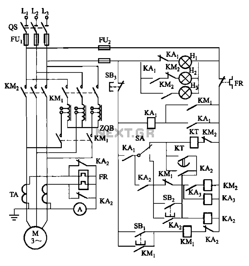
The circuit illustrated in Figure 3-56 features both manual and automatic start-up modes. It incorporates two relays, KA2 and KA3, within the control loop. The circuit design ensures that KM1 is cut off before and after activating KM2. A...

The TDA 7294 from T-MICROELECTRONICS is a monolithic integrated circuit housed in a "Multiwatt 15" package, primarily designed for use in Class AB amplifiers for high-fidelity applications, including stereo systems, active speakers, and television receivers. Its large feed area...
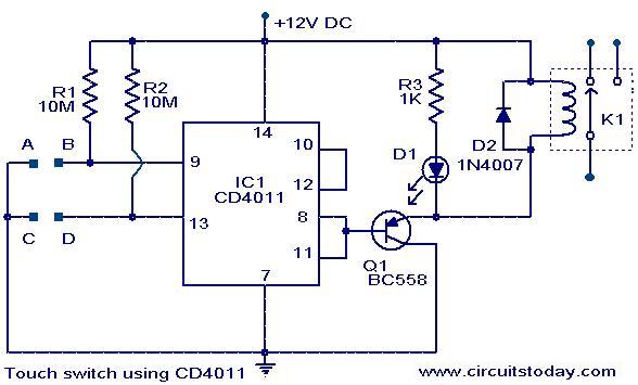
The following circuit illustrates a Touch Switch Circuit Diagram. This circuit is based on the CD4011 IC. Features include R1 and R2, which are the logic gates of the circuit. The Touch Switch Circuit utilizes the CD4011 integrated circuit, which...
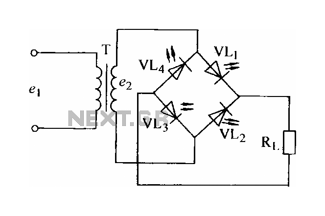
In certain applications, the current from a non-rectified voltage power supply circuit is insufficient. A light-emitting diode (LED) rectifier circuit can be employed to address this issue, serving as a power indicator. It is important to ensure that the...
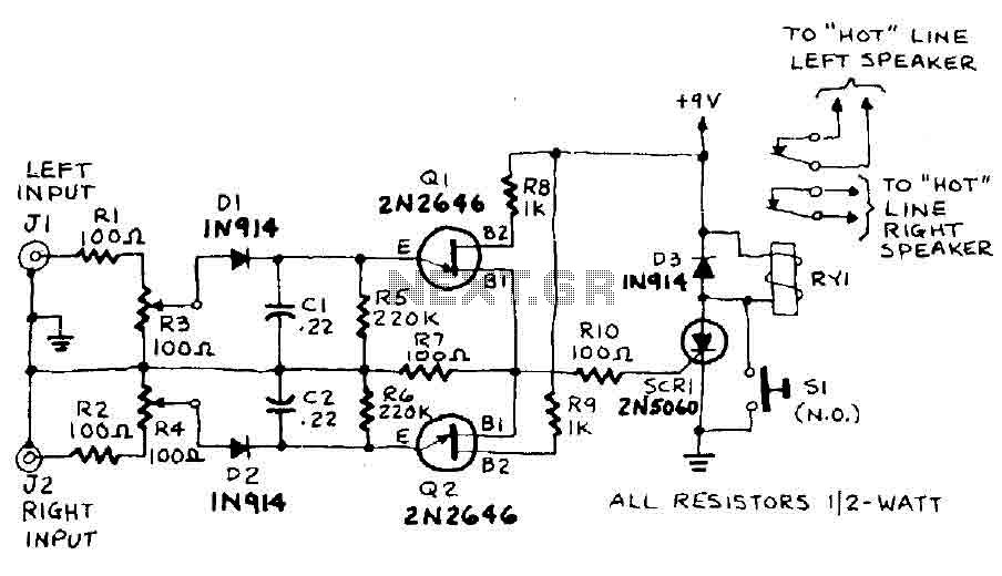
The circuit input is derived from the terminal loudspeaker or amplifier output jacks. If the right channel signal is sufficiently strong to charge capacitor C1 to a potential that exceeds the breakdown voltage of the emitter of transistor Q1,...

This design outlines a phone bug circuit. The wireless telephone line spy circuit is capable of transmitting phone conversations to a nearby FM radio. The circuit must be connected to a standard phone line. In the circuit, the first...