
Long delay schematic with CD4040

The circuit described utilizes a low-frequency oscillator and a binary counter to achieve long timing delays, specifically several hours. The oscillator is implemented using a Schmitt Trigger inverter from the 74HC14 series, which generates a square wave output at approximately 0.5 Hz. This frequency is relatively low, making it suitable for extended timing applications. The inclusion of a 10K ohm resistor in series with the input pin of the inverter serves a protective function by limiting the discharge current of the timing capacitor through the internal protection diodes of the inverter, particularly in the event of a sudden power disconnection.
The core of the timing mechanism is a 12-stage binary counter, specifically the CD4040, which divides the input frequency by two at each stage. This division results in a significant reduction in frequency, allowing the final output stage (Q12) to transition to a high state after approximately one hour. The timing duration can be adjusted by modifying the RC time constant in the oscillator circuit or by selecting different resistor and capacitor values, thereby allowing for flexibility in timing applications.
Each stage of the binary counter changes state in response to the preceding stage transitioning to a low voltage (0 volts). Consequently, the frequency output at each stage is half that of the previous stage, leading to a cascading effect that produces the desired long delay. The circuit can be reset to its initial state by momentarily connecting the reset pin (pin 11) to the positive supply voltage, which sets the counter back to zero and restarts the timing cycle.
It is important to note that the timing accuracy of this configuration may not be as precise as that achieved with a crystal oscillator. Variability in timing can occur, potentially resulting in an accuracy of only 1% to 2%, which is influenced by the stability of the oscillator capacitor. This characteristic should be considered when implementing the circuit for applications requiring high timing precision. Overall, this design presents a practical solution for generating long delays in electronic circuits.Generating long delays of several hours can be accomplished by using a low frequency oscillator and a binary counter as shown below. A single Schmitt Trigger inverter stage (1/6 of 74HC14) is used as a squarewave oscillator to produce a low frequency of about 0.5 Hertz.
The 10K resistor in series with the input (pin 1) reduces the capacitor discharge current through the inverter input internal protection diodes if the circuit is suddenly disconnected from the supply. This resistor may not be needed but is a good idea to use. The frequency is divided by two at each successive stage of the 12 stage binary counter (CD4040) which yields about 1 hour of time before the final stage (Q12) switches to a high state. Longer or shorter times can be obtained by adjusting the oscillator frequency or using different RC values.
Each successive stage changes state when the preceding stage switches to a low state (0 volts), thus the frequency at each stage is one half the frequency of the stage before. Waveform diagrams are shown for the last 3 stages. To begin the delay cycle, the counter can be reset to zero by momentarily connecting the reset line (pin 11) to the positive supply.
Timing accuracy will not be as good as with a crystal oscillator and may only be around 1 or 2% depending on the stability of the oscillator capacitor. 🔗 External reference
Related Circuits

The circuit below demonstrates the generation of a single positive pulse that is delayed in relation to the trigger input time. It is similar to a previously described circuit but utilizes two stages, allowing for control over both the...
The following circuit is an electronic approximation of the gold leaf electroscope, with the added capability of indicating both polarity and electric field magnitude. It is highly sensitive, capable of detecting a television or an electrostatically charged comb from...
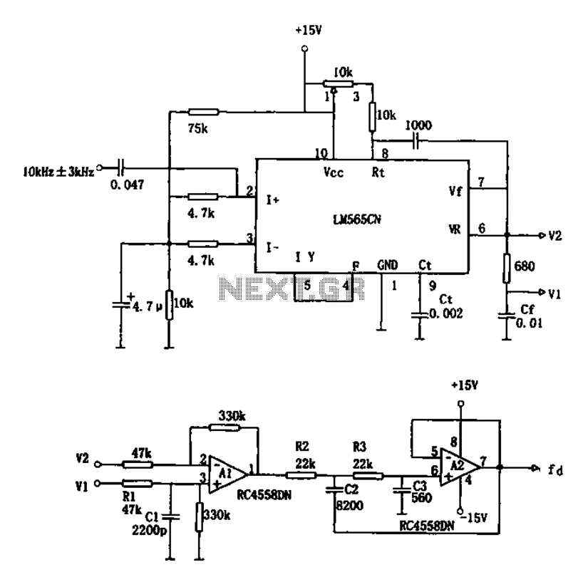
The circuit utilizes a 10 kHz and 3 kHz LM565CN to create an FM demodulation setup. The output diagram (b) illustrates the differential demodulation outputs V1 and V2 from the differential amplifier A1, which provides level displacement and amplification....

The circuit produces a pleasing and accurate imitation of sound, making it suitable for sound effects such as doorbells. It generates a two-tone effect that closely resembles the sound of a cuckoo. This circuit is designed to create a two-tone...
If you need a timer circuit, we go after the most proven 555. However, if the delays are longer, based on timing capacitor capacity is too large. In this case, a circuit of Figure 1 After pressing the button...
The shunt-feedback configuration facilitates the straightforward integration of frequency-dependent networks, enabling a functional and discreet switchable tilt control (optional). When SW1 is in the first position, a gentle shelving bass boost and treble attenuation occur. The central position of...