
Schematic Audio Amplifier Circuit With NCC200 Transistor

The described circuit utilizes high-performance power amplifiers, which are essential for applications requiring significant signal amplification. The PCB (Printed Circuit Board) design facilitates easy assembly and integration into various electronic systems.
The power amplifier circuit typically includes several key components: transistors or operational amplifiers that serve as the main amplification elements, resistors for biasing and feedback, capacitors for filtering and stability, and possibly inductors for additional tuning or load matching.
The layout of the PCB is critical to ensure optimal performance; it must minimize parasitic inductance and capacitance while providing adequate heat dissipation for the power components. The choice of materials for the PCB, such as FR-4 or other low-loss substrates, can also impact the performance characteristics of the amplifier.
In addition to the main amplification components, the circuit may include input and output connectors, power supply circuitry, and protection mechanisms such as fuses or thermal shutdown features to prevent damage to the amplifier under overload conditions.
This power amplifier circuit is suitable for a variety of applications, including audio amplification, RF transmission, and signal conditioning in instrumentation systems. The availability of a complete list of parts simplifies the assembly process, allowing engineers and hobbyists to quickly source the necessary components for their projects.This is a simple circuit but have a high performance power amplifiers. This power amplifier is available as a PCB, with full list of parts to .. 🔗 External reference
Related Circuits
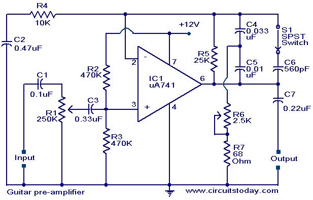
A preamplifier circuit designed for high-impedance electric guitar pickups is presented. This circuit utilizes a uA 741 operational amplifier (IC1) configured as a non-inverting amplifier. The potentiometer R1 functions as a volume control, while potentiometer R6 serves as a...
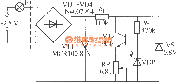
The VDP is a photodiode that exhibits low resistance during the day, approximately 1 kΩ. As a result, transistor VT2 remains off, which keeps thyristor VT1 in the off-state due to the absence of trigger current at the gate,...
This is a police tone circuit for a siren. It is simple and easy to construct. VR1 and VR2 are used to adjust the delay of the siren sound. The design is straightforward and uncomplicated. The police tone siren circuit...
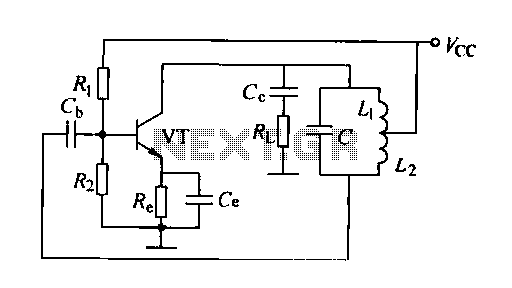
A feedback oscillator circuit utilizing inductance is presented, featuring the 3DG3 transistor. The component parameters reference values include: 1) transistors 3DG6, 2) resistances R1 at 91 kΩ, R2 at 11 kΩ, and R3 unspecified, 3) capacitance values of C...
The following circuit illustrates the Weller WLC100 Electronic Soldering Station Circuit Diagram. This circuit utilizes the Q4012LPH Transistor. Features include safety measures, temperature control, and functionality as a soldering station that performs effectively for various applications. It is a...
This solid-state Tesla Coil design is similar to the two-transistor version available on this site, utilizing a standard flyback transformer to generate high voltage output. Unlike the previous design, it employs a 555 timer to effectively drive a single...