
games timer 2

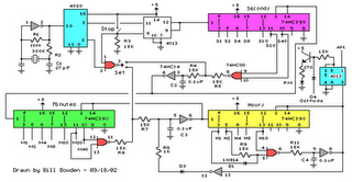
The proposed circuit design encompasses the integration of a 4060 CMOS integrated circuit functioning as an astable multivibrator, generating a stable pulse output for the subsequent 4017 decade counter. The 4060 operates by charging and discharging a capacitor through a resistor, creating a square wave output at its designated output pin. The output frequency can be adjusted by varying the resistor and capacitor values, allowing flexibility in the timing characteristics of the circuit.
The 4017 decade counter receives pulses from the 4060, with its CLOCK input configured at pin 14. Each pulse advances the counter, cycling through its 10 outputs sequentially. The outputs are designed to provide a HIGH signal for a brief duration, which can be visually monitored by connecting LEDs to the respective output pins. The use of 680 Ω resistors in series with each LED is critical for current limiting, ensuring that the LEDs operate within safe parameters.
To further enhance the functionality of the circuit, the RESET and ENABLE inputs are modified to include pull-down resistors. This modification allows for manual control over the counter's operation, enabling the user to reset the counter or enable/disable counting as desired. The incorporation of flying leads facilitates easy access to these inputs for experimentation and testing.
Overall, this circuit design provides a robust solution for creating a games timer, utilizing CMOS technology for reliability and efficiency. The systematic approach to adding components, coupled with the ability to monitor outputs through LEDs, ensures effective troubleshooting and validation of circuit performance.Circuits using large value resistor/capacitor combinations are not very accurate because of the wide tolerance and leakage current of polarised capacitors. A better solution is to use an astable circuit together with a binary counter/divider chain which reduces the frequency of the astable pulses.
The 4060 cmos integrated circuit is ideal for the games timer application. In this session, you will investigate how to set up the counter/display subsystem of the games timer using another cmos integrated circuit, the 4017 decade counter. To find out about the 4017, you need a source of pulses. You could use the 4060 astable circuit investigated in the previous session, but it is more convenient to build a temporary alternative circuit.
About the easiest way of building an astable is using a special type of NAND gate, called a Schmitt trigger NAND gate. Here are the symbols for normal and Schmitt trigger gates: The Schmitt trigger gate has two different thresholds.
If the voltage applied to one of the inputs to the gate starts at 0V and is slowly increased, the logic 1 threshold, when the input starts to count as a HIGH voltage, is around two-thirds of the power supply voltage, that is, about 6V with a 9V supply. On the other hand, if the voltage connected to the input starts at 9V and is slowly decreased, the logic 0 threshold, when the input counts as a LOW voltage, is around one-third of the power supply voltage, or about 3V.
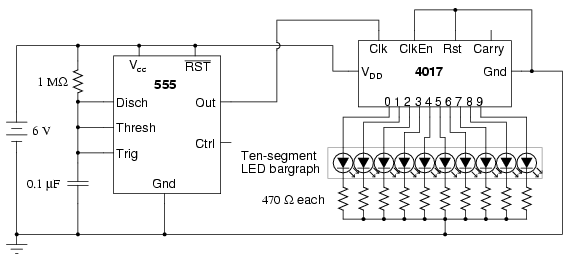
This difference in thresholds allows you to use a Schmitt trigger gate as the basis for an extremely simple astable circuit. The 4017 is a divide-by-10, or decade counter, with 10 individual outputs which go HIGH in turn when pulses are fed to its CLOCK input.
The connection details for the 4017 are: To make the 4017 work, you need to connect the power supply pins (`beasties` need power supplies). In addition, you need to connect the ENABLE and RESET inputs to 0 V. With these connections in place, the pulses from the 4093 astable can be connected to the CLOCK input, pin 14.
Provided you have built the circuit correctly, each of the 10 individual outputs of the 4017 should be pulsing. You should notice that the pulsing is slower and that each output is HIGH for a short time. Now you are going to add LEDs to monitor the outputs of the 4017 counter. The best way of doing this is to add the LEDs one at a time and to check that each lights up at the correct moment in the counter cycle before adding any more LEDs.
This way of working is extremely efficient. You know whether the circuit is working and, if there are any faults, you can correct them at once. To work out where exactly the LEDs should be connected, you need to refer back to the pin connection diagram for the 4017. This shows that output 0 of the counter is located at pin 3. You need a wire link from pin 3 to the first LED: Similarly, output 1 is located at pin 2, so you need a wire link from pin 2 to the second LED.
The 680 W resistors limit the current flowing through the LEDs to around 10mA to avoid damage, either to the LEDs, or to the 4017. You will need to connect a second small prototype board to make room for all the LEDs. Add additional LEDs each with its own series resistor in the correct sequence, again following the pin connection diagram : You are going to modify your circuit to investigate the effects of the RESET and ENABLE inputs.
When the counter is free-running, these inputs are connected to 0 V. The circuit needs to be altered so that, instead of being connected directly to 0 V, each of these inputs is connected to 0 V through a 10 kW pull-down resistor: A flying lead is just a piece of wire connected into the circuit at one end. If the free ends of the flying leads are left unconnected, the RESET and ENABLE inputs are held LOW as before.
However, if the free end of a flying lead is conn 🔗 External reference
Related Circuits
The circuit was designed to create an alarm system that alerts a sleeping person to prevent snoring by utilizing a vibrator instead of an audio alert. The circuit operates on the principle of detecting snoring sounds through a microphone or...
The following circuit illustrates a Cat and Dog Repellent Timer Circuit Diagram. Features include the capability to maintain a deep cycle battery charged by a solar panel. The Cat and Dog Repellent Timer Circuit is designed to provide a humane...
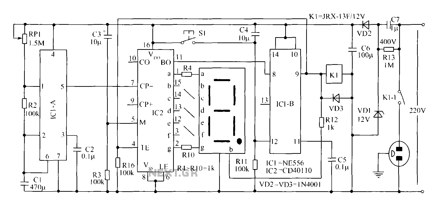
A novel timing switch circuit features a "Variable Timing" adjustment function in addition to a standard timing circuit. It also includes a countdown display feature, which indicates the remaining time of the timing circuit, making it particularly useful. The...
The figure illustrates a preset outage timer circuit designed for an electric cooker. The timing range of the circuit extends from 1 hour to 12 hours, adjustable via a potentiometer (PR). The timing mode operates on a counting basis,...
The following circuit illustrates a schematic diagram of an LED sequencer. This circuit is based on the 555 timer integrated circuit (IC). Features include a 555 timer circuit designed to debounce a mechanical switch, a 555 timer circuit to...
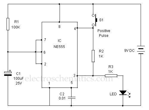
This 555 timer is designed uniquely to provide a positive output through control over its reset pin. Typically, the 555 timer IC is triggered by applying a negative voltage. The 555 timer is a versatile integrated circuit widely used in...